Fire detectors behind the suspended ceiling. Fire protection behind a false ceiling. Rules for installing fire detectors on a false ceiling
A few years ago, in the industry media and on portals for fire safety there were many publications devoted to the problem of implementing technical solutions for fire protection of the overhead space. The so-called double-sided fire smoke detectors were subjected to serious criticism, and the traditional way of protecting the space above the ceiling with the help of detectors installed on the main ceiling had known difficulties in maintaining such detectors.
An innovative solution to this problem was patented in 2005 by the private enterprise "Arton", first as a Ukrainian invention No. 73398 "Smoke fire detector". Then similar technical solutions were patented both in Russia and in the Eurasian Patent Office (patents No. 2265888 and 007944). And the main thing was that consumers were offered several options for a two-point smoke detector, each of which had two processing units spaced apart in space.
Several options were also presented in the claims design two-point detector. Distinctive features among other technical solutions is that, in addition to the main processing unit, the two-point detector contains one more additional smoke processing unit. Both processing units are located on the same vertical axis, turned to each other by the bases and rigidly connected to each other.
The design of two-point detectors IP-2.1, IP-2.2 (Fig. 1) turned out to be the most suitable for implementation in conditions of mass production. These detectors differ from each other only in the connection scheme to the fire alarm loop: IP-2.1 is connected using a two-wire circuit, and IP-2.2 - using a four-wire circuit.
Fig.1
To implement this task, it was necessary to develop special base bases that would ensure not only the connection of the detectors to the alarm loop, but also the passage of the upper processing unit of the two-point detector through them.
IP-2.1 is connected to the fire alarm loop using the base base B103-02 (Fig. 2), in which contacts are used that correspond to Ukrainian patents for inventions No. 85211 and 87554. IP-2.2 is connected via four-wire circuits using the B103-03 base base (Fig. 3) with one break contact.
 |
 |
| Rice. 2 | Rice. 3 |
These base bases have a significant through hole allowing the top processing unit of the two-point detector to be inserted through it. And for this it is necessary that the inequality is fulfilled:
Ø A ≥ Ø B, Ø A ≥ Ø C,
|
where Ø A is the minimum transverse size of the through hole of the base base; Ø B - the maximum transverse dimension of the additional processing unit; Ø C - the maximum transverse dimension of the rod. The block diagram of a two-point detector is shown in fig. 4, where 1 - main processing unit; 2 - base; 3 - electronic block; 4 - detector contacts; 5 - indicator; 6 - optoelectronic sensor; 7 - smoke chamber; 8 - base base; 9 - fire alarm loop; 10 - external indicator; 11 - contacts of the base base; 12 - additional processing unit; 13 - the basis of the additional processing unit; 14 electronic unit of the additional processing unit; 15 - optoelectronic camera of the additional processing unit; 16 - smoke chamber of the additional processing unit; 17 - conductors connecting electronic units; 18 bar. |

Rice. four
The bottom processing unit of a two - point detector mates with the base base using traditional fire detector contacts . The base base can be installed in a decorative ring (see fig. 1), which hides the unevenness of the opening in the false ceiling. Lay and fasten the wires of the fire alarm loop into the base base so that the through hole in it remains free and the conductors do not interfere with the introduction and location of the two-point detector in it.
The circuitry solutions used in these detectors are also protected by patents for inventions of Ukraine No. 81529, 85270 and 85273. The first of them is devoted to the temperature stabilization of the power of infrared radiation. The second one is stabilization of current consumption in various modes of operation of the detector, while generating various optical signals with yellow and red indicators. And the third patent is responsible for matching the analog inputs of the microcontroller with the outputs of infrared photodetectors. The detectors provide periodic holding self-diagnostics, control the state of the smoke sensor chambers that provide compensation for drift (dustiness of the smoke sensor chambers) and, if necessary, generate optical signals “Fault” with a yellow indicator. This indication indicates the need for detector maintenance.
In total, the two-point detector can be in seven operating modes, and the yellow and red indicators display these operating modes of both sensors:
- Duty;
- Upper sensor fire;
- Lower sensor fire;
- Fire of the upper and lower sensors;
- Upper sensor malfunction;
- Lower sensor malfunction;
- Faulty upper and lower sensors.
IP-2.1 and IP-2.2 detectors are manufactured in three versions according to the distance between the sensors of the main and additional processing units: 200, 400 and 600 mm. It is this size that reaches the restrictions on the height of the suspended ceiling of those rooms where such detectors can be used. The procedure for removing the product for maintenance is no different from removing a conventional point detector.
The connection of the IP-2.1 detectors to the control panel with a constant current loop is carried out according to the scheme shown in fig. 5. Due to the use of current stabilization at outputs 1 and 2 of the detector, the number of elements that are installed on the base bases is minimized.

Rice. 5
The IP2-1 detectors are connected to the control panel with an alternating loop according to the scheme shown in fig. 6. By connecting pins 1 and 2, the current from the positive phase of the loop state is doubled.

Rice. 6
In the case of using detectors IP2-2, it is necessary to install a resistor Rv in each base, which is connected in parallel with the contacts of the detector relay. In addition, it is imperative to install the terminal device UK-4 at the end of each loop. Only when the detector is disconnected from the base base, a fault signal will be generated on the control panel.

Rice. 7
The use of two-point detectors in Ukraine is also reflected in state building codes. So, Appendix B of DBN V.2.5-56: 2010 provides a definition:
"A two-point fire detector is a fire detector that contains in its design two sensitive elements located on the same vertical axis and structurally fastened to each other so that when they are installed in the base, one of them will be above the base, and the second, on which indicators are located the states of both sensitive elements are under the base".
And in paragraph 6.2.13 of this document there is a note: "To protect rooms with suspended ceilings up to 0.9 m high, inclusive, two-point fire detectors can be used."
Literature:
- Popov M. "What do you have in the ceiling space?". 03.12.2002
- "Explain to a newbie" discussion on the Security-bridge forum
- Bakanov V. "Innovative solution for fire protection of premises with false ceilings", j. Pozhezhna bezpeka, 2008 No. 6, - p. 28.
- Patent of Ukraine for the invention No. 73398 "Smoke fire detector", bull. No. 7, 2005
- Patent of Ukraine for the invention No. 85211 "Contact of the base of the fire detector", bull. No. 1, 2009
- Patent of Ukraine for the invention No. 87554 "Contact of the base of the fire detector", bull. No. 14, 2009
- Maslov I. "Contact? There is contact! For how long..." J. BDI, 2005, No. 1, - p. 17
- Patent of Ukraine for the invention No. 81529 "Smoke fire detector", bull. No. 1, 2008
- Patent of Ukraine for the invention No. 85270 "Smoke fire detector", bull. No. 1, 2009
- Patent of Ukraine for the invention No. 85273 "Smoke fire detector", bul. No. 1, 2009
- DBN V.2.5-56:2010 Engineering equipment of buildings and structures. Fire protection systems.
Part 2
Returning again to the topic of protecting the overhead space, it is advisable to recall that innovative solutions - point-to-point detectors IP-2.1 and IP-2.2 have repeatedly passed certification tests both in Ukraine for compliance with the DSTU EN 54-7 standard, and in Russia according to technical regulations and relevant sections of GOST R 53325.
The fate of these products in Russia was very difficult, since pseudo-innovative solutions already existed there - bidirectional detectors. Moreover, they existed contrary to the laws of physics and thanks to the "letters of happiness" that were issued by officials from the Ministry of Emergencies. So the manufacturer IP212-3SU advertised the mentioned product as the only detector in Russia that can be used to simultaneously control both the main room and the inter-ceiling space up to 1 m high thanks to special slots in the detector housing (Fig. 8), where:
- detector IP212-3SU;
- bottom slots;
- upper slots;
- suspended ceiling;
- mounting device.

Rice. eight
This possibility was confirmed by a letter from VNIIPO, St. Petersburg branch No. 06-03/97 dated February 3, 1999 false ceiling detectors IP 212-3SU. However, one of the authors of the mentioned letter from VNIIPO, namely Sychev Sergey Vasilievich, in his letter to the Internet newspaper OXPAHA.ru, stated that VNIIPO specialists carried out comparative tests of detectors on a suspended ceiling at its various heights - from 0.5 to 1 m. Results of these tests were negative (the detectors did not work). And the only fact confirmed by experiments, which is mentioned in the letter from VNIIPO, is that these detectors detect smoke better than thermal ones. By the way, the negative test results were confirmed not only by observations, but also by measurements and video filming of the spread of smoke behind the false ceiling!
Probably, because such a pseudo-innovative solution was not patented, the number of manufacturers of fire detectors rapidly increased, which at the beginning of the century sought to introduce such a “novelty” into circulation as soon as possible. The real struggle of business owners with the elementary laws of physics for possible profit began. And it doesn't matter anymore that smoke as a product of combustion has a higher temperature than the surrounding air, and in rooms it spreads along the ceiling.
It turns out that it is possible to obtain a completely legitimate solution that for a single detector, in a single case, the laws of physics do not apply: for this detector, smoke spreads across the floor. This is how new "letters of happiness" appeared for new manufacturers ...
Several good reasons why a bidirectional vertical purge detector cannot be used to control not only the interceiling space, but also the main room, were mentioned in the article by Maxim Popov. However, this publication did not offer any new solution to this problem of protecting the space behind the ceiling.
An attempt to solve this problem was the proposal of the specialists of CJSC "ARGUS-SPEKTR", who patented the invention No. 2178919 "Device for detecting fire in rooms with interceiling space" . They suggested using one detector 1 to control two spaces separated by a suspended ceiling (Fig. 9). This detector 1, installed on the main ceiling 5, was connected to a smoke channel - a pipe 2 of the appropriate length and a given inner diameter. Pipe 2 was installed vertically between detector 1 and hole 3 in the false ceiling. From the false ceiling side, a special deflector 4 was installed in the smoke channel, which ensured the unhindered passage of smoke from the main room through the smoke channel 2 to the detector 1. An appropriately sized gap between the upper end of the pipe 2 and the detector 1 provided access to it for smoke that could arise in ceiling space. The detector status was monitored using external device optical signaling (VUOS) 6, placed on the outer side of the false ceiling.
However, for ten years CJSC "ARGUS-SPEKTR", which masters many new products, could not bring this technical solution to the serial production of technical means suitable for protecting divided spaces. Perhaps the mentioned technical solution is unsuitable for practical implementation, since the problem of maintenance of the detector installed in the overhead space is not solved by this patent.

Rice. 9
The real start of the use of two-point detectors in Russia was facilitated by the publication of Igor Gennadievich Neplokhov. And to meet the requirements of the regulatory documents of the Russian Federation, a special version of the two-point detector was also developed - IP-2.4, which was connected to two fire alarm loops, galvanically separated from each other. In such detectors, additional innovative solutions are used. Firstly, it is a basic base with two break contacts. If the detector was disconnected from the basic base, a malfunction occurred in two fire alarm loops. Secondly, the detector had two independent red indicators for the fire alarm status for each processing unit and a yellow indicator for indicating other detector states. Thirdly, in order to return the detector to its original state, it was necessary to reset the supply voltage on both loops simultaneously or separately for each loop that was in a fire alarm state. Of course, such a detector was more expensive than the IP-2.1 detector, which was connected to one fire alarm loop. There is simply no other way out. If more additional conditions must be fulfilled by the detector, then it becomes more complicated and its price naturally increases. However, this path does not suit all manufacturers.
Again there are those who wish to neglect the objective laws of physics and economics. So on the website of a well-known manufacturer in Ukraine and Russia, a new pseudo-innovative solution of the "ceiling detector" appears (see Fig. 10). A study of the mounting instructions for the "Set of mounting parts for the ceiling-mounted detector" allows us to conclude that the consumer is provided with a combination of certified products, which itself could never be certified.

Rice. ten
The mounting kit for the overhead detector includes two certified fire smoke detectors. But in this set, the location of smoke detectors in space is not the same! One would like to ask the manufacturer of this "novelty": does the laws of physics again operate in the overhead space?
The fact that the manufacturer of this kit did not conduct certification tests of such a product as a type 1 component in accordance with GOST pr EN 54-13: 2004 is so obvious. There is no certificate on the manufacturer's website, but it should be for a product of this type!
This manufacturer did not conduct qualification tests of the kit either, because in the process of testing according to clause 5.3 "Dependence on the direction" of DSTU EN 54-7:2003 or according to clause 4.7.2.7 of GOST R 53325-2009 for a smoke detector, it would be impossible to obtain positive results. The detector located in the smoke channel, as the top of the set, would show such a figure-of-eight radiation pattern in which the ratio of the response threshold values would be guaranteed to be greater than 1.6. If the detector is returned with its base to the air flow, then its sensitivity will be 3-4 times less than in the direction of maximum sensitivity. It is also known that this asymmetry will manifest itself even more with a decrease in the air flow velocity. Thus, even during tests for test fires, according to clause 5.18, this set will not meet the acceptance criteria.
Knowing how difficult it is to test detectors for test fires, one can only guess what the test results of such a kit could be. To avoid these inconsistencies with DSTU EN 54-7:2003 and GOST R 53325-2009, it would be possible to change the position of the upper detector so that both detectors face each other with their base bases. But such a solution falls within the scope of the claims UA73398. And the manufacturer of the kit does not plan to acquire a license from the patent holder, so he offers consumers - installers and designers - a non-certified technical solution based on certified detectors. But the responsibility for the application of such a pseudo-innovative solution lies with those who will use it in their projects.
From the above examples, it can be seen that not all inventions are implemented, but really innovative solutions are backed by one or more patents for inventions, but pseudo-innovative solutions do not have such support.
Literature
- DSTU EN 54-7:2004 Fire alarm systems. Part 7.
- GOST R 53325-2009 Fire fighting equipment. Technical means fire automatics. General technical requirements. Test Methods
- Letter regarding M. Popov's article. 02/05/2003.
- Russian patent for invention No. 2178919 "Device for detecting fire in rooms with interceiling space", bul. No. 4, February 2002
- Two-point fire smoke detector for divided spaces IP-2.4. MCI passport 425239.004 PS
- Installation instructions AKPI.425921.004IM3. A set of mounting parts for a ceiling-mounted detector.
- Bakanov V. "A look at fire smoke detectors through the prism of test fires" j. F + S: Safety and fire protection technologies. - 2010, - No. 1, p. 26.
Good afternoon, Dear Readers and Colleagues! The topic of our discussion today is fire protection behind a suspended ceiling. The question is the following - as has been said more than once in our topics, fire safety standards are in constant active transformation and can undergo changes up to several times in one calendar year. Therefore, it is necessary to constantly keep abreast of relevant documents and the latest adopted changes to these relevant documents. This article is more written for the category of Readers - "Owners of buildings and structures" than for normatives or experienced designers. The fact is that many of the owners of the premises are still confident that it is the height of the space above the ceiling that is the dictating factor for determining the need to install fire detectors there (behind the ceiling). That is, if more than 40 centimeters, then it is necessary to install detectors, and if less than 40 centimeters, then fire protection behind the false ceiling is not needed. Even during the construction (finishing) of the premises, the Owners set the conditions for the builders to minimize the heights beyond the ceiling space based on the critical distance - 40 centimeters. This is not true. Today, fire protection behind a false ceiling does not depend on the height of the ceiling space! fire protection behind a false ceiling (and not only its presence, but the type of protection itself) depends solely on the presence and amount of combustible cable and other loads in the ceiling space.
For starters, let's take regulatory framework- SP5.13130.2009, Appendix “A” (mandatory), table “A2”, paragraph 11, and also see the note to paragraph 11 under the plate - standard “ .
11 Spaces behind false ceilings and under double floors
when laying air ducts, pipelines with insulation in them, you
made of materials of the flammability group G1 -G4, as well as cable
lei (wires) that do not spread combustion (NG) and have a code
fire hazard PRGP1 (according to), including when they are joint
gasket(2) :
11.1 Ducts, pipelines or cables (wires) with volume
combustible mass of cables (wires) 7 or more liters per meter of cable-
line (CL), including when they are jointly laid - are equipped with APT installations, n regardless of area and volume;
11.2 Cables (wires) of the NG type with a total volume of combustible mass from
1.5 to 7 liters per meter of cable lines - equipped with APS installations, regardless of area and volume.
Note (2):
1 Cable installations, spaces behind suspended ceilings and under double floors are automatically novki are not equipped (with the exception of paragraphs 1-3):
a) when laying cables (wires) in steel water and gas pipes or steel solid boxes with open waving solid covers;
b) when laying pipelines and air ducts with non-combustible insulation;
c) when laying single cables (wires) of the NG type for powering lighting circuits;
d) when laying cables (wires) of the NG type with a total volume of combustible mass of less than 1.5 liters per 1 meter of cable lines behind suspended ceilings made of materials of flammability group NG and G1.
2 If the building (premises) as a whole is subject to AUPT protection, the spaces behind false ceilings and under double floors when laying air ducts, pipelines with insulation made from materials of the go group flammability G1-G4, or cables (wires) with a volume of combustible mass of cables (wires) of more than 7 liters per 1 meter of CL is necessary protect with appropriate settings. Moreover, if the height from the ceiling to the false ceiling or from the black level floor to the level of the double floor does not exceed 0.4 m, the AUPT device is not required.
3 The volume of combustible mass of insulation of cables (wires) is determined according to the method of GOST R IEC 60332-3-22.
Now let's decipher all this clear and plain language. We look behind the suspended ceiling, we see a cable for powering lighting networks (ceiling lamps), it is also possible some kind of cable for socket groups, maybe there is a power cable to floor lighting panels or others electrical panels, may be a communication cable or computer cables or control cables for any engineering systems or some wires burglar alarm. We choose a section of the cable route, where all these cable products are collected as much as possible, laid in one direction for at least one meter, we count the number and brands of cables and wires and carefully write down the data in a notebook. Next, we turn to the directories of cable manufacturers (I recommend the directory of the Kolchuginsky Plant, which can be very easily found on their website) and opposite each of the cable brands laid behind the suspended ceiling and written out in a notebook, we write down the combustible mass index by 1 running meter the appropriate cable or wire taken from the specified directory. I will give some of the data I have on the combustible mass of cable products per meter - download here and use in the calculations. Further - just arithmetic, i.e. for example, a bunch of 10 pieces cable brand VVGNG-LS VVGng-LS TU 16.K71-310-2001 round conductors 0.66 kV2x1.5 with combustible mass 0,044 liters per 1 linear meter will be 10 x 0.044 = 0.44 l / 1 meter CL. That's it - it's simple. Further, in a similar way, we consider the communication cable, then the computer cable, and so on. Further, we add up all the data received - for example, from power circuits - 0.44, plus from computer circuits - 0.55, plus from the communication cable - 0.70, plus from control cables - 0.55. Total means - 0,44+0,55+0,7+0,55 = 2,24 liters / 1 running meter KL. Here is the number 2,24 and is the combustible load parameter we are looking for.
Now we turn to the text of the above-described standard “fire protection behind a suspended ceiling”:
If an NG cable is laid behind the ceiling and the combustible load is up to 1.5 liters per 1 meter of cable, then there is no need to install detectors behind the false ceiling, that is, it is not needed;
If the cable of the “NG” brand is laid behind the ceiling and the combustible load is in the range from 1.5 to 7 liters per 1 meter of CL, then it is necessary to protect the substation in the ceiling space, i.e. required in the form of an independent overhead fire alarm cable;
If a cable of the “NG” or not “NG” brands is laid behind the ceiling (it doesn’t matter here already) and the combustible load is more than 7 liters per 1 meter of CL, then the space behind the suspended ceiling is necessary for PT, i.e., fire protection behind the suspended ceiling in type of fire extinguishing system. The exception is the ceiling space with a height of less than 0.4 meters - there is no APT done (see carefully the appendix of the norms - set out above), and there the APS cable is simply mounted, as if the combustible load would be within the limits of 1.5 to 7 liters per 1 linear meter KL.
If a cable not “NG” is laid behind the ceiling, and you do not want to install a fire extinguisher, then you must either replace this cable with “NG” or place this cable in metal pipes or metal blind boxes. In this case, the installation of overhead fire detectors does not compensate for the violation in the form of using a non-NG cable behind the ceiling, not laid in pipes or ducts. Only fire extinguishing can compensate for such a violation.
Well, actually, all the calculations - everything is extremely simple and does not raise questions. If you still have questions or clarifications or objections, then write in the comments - we will consider and continue the dialogue. If everything is clear and good - put "like" - to support our desire to continue to write similar articles. I authorize copying my article “Fire Protection Behind a False Ceiling” for publication on other resources, provided that all links to our site are preserved in the text. As usual, I invite you to read our other articles at the links:
- how many fire detectors should be installed in a compartment limited by beams of more than 0.4 meters?
– cable penetrations "Stop-fire"
- fire detector on the wall
– smoke exhaust systems, compensation
– initial data for design
– shutdown of ventilation in case of fire
– wall-mounted sounders in rooms with a height of less than 2.45 meters
- fire detectors in the ceiling compartment with beams over 0.4 meters (clarification)!
– fire safety requirements for underground parking
– new regulations
– fines for violations in the field of fire safety
– calculation of sound pressure at the object
Technical report - what is it for?
Addressable fire detector - how much per room?
I wish you all a constant increase in the level of knowledge of regulatory documents and success in your work!
Our group Vkontakte - https://vk.com/club103541242
We are in Odnoklassniki - https://ok.ru/group/52452917248157
We are on Facebook - https://www.facebook.com/NORMA-PB-460063777515374/timeline/
We are in Yandex-ZEN - https://zen.yandex.ru/id/5c86022fcd893400b3e4ea8c
Post navigation
: 17 comments
-
And what if, in addition to cables, water supply pipes are laid under the ceiling - polypropylene material in K-flex insulation, sewerage pipes made of polypropylene?
Where to get this data to calculate the combustible load
-
For me, the following is missed in the article: the volume of combustible load is considered only for NG cables, and values up to 1.5; from 1.5 to 7, and more than 7 liters per meter of cable lines will be valid only if the cable lines of the overhead space are made using NG cables. The presence of at least one non-NG cable or wire (TRP, KPSVV, etc.) no longer gives the right to exclude even if the amount of combustible load is less than 1.5 liters. Please do AUPS. or hide such cables in a met pipe, etc.
- Post Author
Hello! You are slightly wrong. You write “it is considered only for “NG” cables, and values up to 1.5; from 1.5 to 7, and more than 7 liters per meter K”.
Let's read the paragraph again verbatim:
11.1 Air ducts, pipelines or cables (wires) with volume
combustible mass of cables (wires) 7 or more liters per meter of cable-
line (CL), including when they are jointly laid - are equipped with APT installations, regardless of area and volume; ... .... AS YOU SEE, IF THE WIRES AND CABLES ARE NOT “NG” AND THE VOLUME EXCEEDS 7 LITERS, THEN FIRE EXTINGUISHING SHOULD BE DONE, AND not only for “NG”, as you write above ..
The positions in the note up to 1.5 liters and from 1.5 to 7 liters are really considered only with the use of a “NG” type cable.
11.2 Cables (wires) of the NG type with a total volume of combustible mass from
1.5 to 7 liters per meter of cable lines - regardless of the area of the AUPS. and in the note item NOT EQUIPPED d) when laying cables (wires) of the NG type with a total volume of combustible mass of less than 1.5 liters per 1 meter of cable lines behind suspended
ceilings made of materials of flammability group NG and G1.
THE OUTPUT IS THIS:
- IF THERE IS A NON-NG CABLE AND THE FLAMMABLE LOAD EXCEEDS 7 LITERS, FIRE EXTINGUISHING SHOULD BE DONE.
- IF THERE IS A CABLE NOT “NG” AND A FLAMMABLE LOAD OF LESS THAN 7 LITERS AND LESS THAN 1.5 LITERS PER METER OF THE CABLE LINE, THEN THIS OPTION IS NOT PROVIDED BY REGULATIONS IN PART OF THE MANUAL WHAT SYSTEMS IN THIS CASE TO DO APS OR APT OR NOTHING IS NEEDED AT ALL AND THIS DOES NOT MEAN WHAT YOU NEED TO DO AUPS AND EVERYTHING - WITH WHAT JOY IS IT?
- IF THE CABLE is “NG”, THEN AN ALARM IS PROVIDED (WHEN A BURNING LOAD FROM 1.5 TO 7 LITERS) AND NOTHING SHOULD BE DONE AT A LOAD OF UP TO 1.5 LITERS.
Your suggestion “Please do AUPS. or hide such cables in a meth pipe, etc.” nothing is substantiated. WHY IS IT ASKED TO DO AUPS AND NOT AUPT? BECAUSE YOU LIKE IT SO MUCH??? This is not true, you just need to either change the cable to “NG” or lay the existing “NOT NG” cable in metal pipes or boxes in order to fall under paragraph “a” of the application……i.e.
a) when laying cables (wires) in steel water and gas pipes or steel solid boxes with open
waving solid covers; AS YOU SEE HERE, THERE ARE NO REQUIREMENTS FOR “ng”.
- Post Author
Requirements for fire protection of spaces behind false ceilings and under double floors have appeared relatively recently, but have managed to undergo a number of significant changes. At present, the type of automatic fire fighting system is determined based on the volume of the combustible mass of one meter of cable line. The article presents methods for determining the volume of combustible cable mass and discusses the development of technical solutions used to protect spaces behind false ceilings and under double floors. These spaces, in contrast to the main premises, are characterized by more difficult conditions: Difficulties in installation and maintenance Presence of air currents, dust, etc. This determines the search for special technical solutions that provide a high level of protection while reducing the overall cost of installation and maintenance.
REQUIREMENTS FOR NPB 110-03
As in the general case, the level of protection required for spaces behind false ceilings and under double floors depends on the magnitude of the fire load, taking into account its specifics. If there is practically nothing to burn, then protection is not required, a relatively small volume of an automatic fire alarm installation (AUPS) is sufficient, a large volume of automatic fire extinguishing installation (AUPT) is required. According to the previous version of NPB 110-99 "List of buildings, structures, premises and equipment to be protected by automatic fire extinguishing installations and automatic fire alarms" p. 3.11. Spaces behind false ceilings and double floors when laying air ducts, pipelines or cables (wires) in them, including when they are jointly laid, with a number of cables (wires) of more than 12 with a voltage of 220 V and above with insulation from combustible and slow-burning materials, regardless of area and volume required AUPT, and when laying from 5 to 12 cables (wires) with a voltage of 220 V and above, AUPS was required regardless of the area. It was allowed not to protect the space behind suspended ceilings and under double floors when laying cables (wires) in steel water and gas pipes, when laying pipelines and air ducts with non-combustible insulation, and when laying cable routes with the number of cables and wires less than 5 with a voltage of 220V and more with insulation made of combustible and slow-burning materials. Those. or the ceiling space must be isolated from the cable steel pipe, which will not allow the spread of fire, or the cable itself must burn.
Of course, the number of cables (wires) is weakly related to the fire load, for example, it was possible not to protect the overhead space if 4 power cables type VVG 1x1.5 (section 1.5 mm2) with a diameter of 5 mm and if 4 power cables of type VVG 1x240 (section 240 mm2) with a diameter of 27.7 mm are laid. In 2003, these requirements were significantly changed: the criterion in the form of the number of wires, which was previously used to determine the choice of protection level, was replaced by the total volume of combustible mass. In the current NPB 110-03 according to clause 11 of Table 2, the spaces behind suspended ceilings when laying air ducts, pipelines with insulation made from materials of the combustibility group G1-G4, as well as cables (wires) that do not spread combustion (NG ) and having a fire hazard code PRGP1 (according to NPB 248), including when they are jointly laid with a total volume of combustible mass of 7 or more liters per 1 meter of cable line, they are protected by fire extinguishing systems, with a total volume of combustible mass from 1.5 to 7 liters per 1 meter of cable line - fire alarm. It also states that the volume of the combustible mass of cable (wire) insulation should be determined according to the method approved in the prescribed manner.
Spaces behind false ceilings and under double floors are not equipped with automatic installations when laying cables (wires) in steel water and gas pipes or steel solid boxes with openable solid covers, when laying pipelines and air ducts with non-combustible insulation, when laying single cables (wires) of the NG type for powering lighting circuits and when laying cables (wires) of the NG type with a total volume of combustible mass of less than 1.5 liters per 1 meter of cable line behind suspended ceilings made of materials of the NG and G combustibility groups. Moreover, if the building (room) as a whole AUPT is subject to protection, the space behind suspended ceilings, when laying air ducts, pipelines with insulation made of materials of the G1-G4 combustibility group or cables (wires) with a volume of combustible mass of cables (wires) of more than 7 liters per 1 meter of the cable line, must be protected with appropriate settings, but if the height from the ceiling to the false ceiling does not exceed 0, 4 m, then the installation of a fire extinguisher is not required. Fire alarms are used regardless of the distance between the ceiling and the false ceiling.
VOLUME OF COMBUSTIBLE MASS OF THE CABLE LINE
A cable line can consist of a different number of cables of several types (Fig. 1) and in order to calculate the volume of combustible mass of a cable line, it is necessary to have the value of the insulation volume of each type of cable. As a rule, the cable has several layers of insulation made of various materials and various sizes. For example, a low-voltage multi-core lancabel has multi-colored polyethylene insulation of copper cores and an outer sheath made of polyvinyl chloride plastic compound (Fig. 2).
Rice. 1. Fragment of a cable line
The method for determining the volume of the combustible mass of the cable, given in the Explanation to NPB 110-03, was taken practically unchanged from GOST R IEC 332-3-96 “Testing cables for non-flame propagation. Testing of wires or cables laid in bundles”, namely clause 2.3. The technique is universal and, as a result, quite complicated and can actually be used, perhaps, only for certification tests, otherwise it is difficult to ensure and confirm the reliability of the results obtained. Obviously, due to the lack of standardized methods for directly measuring the volume of cable insulation, its value is determined based on the mass and density of cable insulation samples.
Rice. 2. Lankabel construction.
For measurement, a cable sample with a length of at least 0.3 m is taken with cut surfaces perpendicular to the cable axis to ensure an accurate measurement of its length. The sample is disassembled into its constituent elements and the weight of each non-metallic material is determined. Non-metallic materials, the mass of which is less than 5% of the total mass of non-metallic materials, may be ignored. If the electrically conductive screens cannot be removed from the insulating material, these components are taken as one unit when measuring their mass and determining density. Further, the density of each non-metallic material (including porous materials) is determined by the appropriate method and, as an example, a link is given to section 8 of GOST 12175 " General Methods testing of insulation and sheath materials electrical cables. Density determination methods. Water absorption and shrinkage tests. In this GOST, the main method for determining the density of materials is the suspension method given in clause 8.1., According to which in ethyl alcohol (to determine the density of less than 1 g / cm cm3) place three pieces of cable insulation 1-2 mm long. Distilled water is then added until the sample is suspended in the liquid. Then, the density of the liquid is determined with a hydrometer and recorded to the nearest three decimal places as the density of the test samples. According to the Explanation to NPB 110-03 and according to GOST R IEC 332-3-96, it is sufficient to determine the density values with an accuracy of the second decimal place, and for tape and fibrous materials, the density values \u200b\u200bare taken equal to 1.
PROTECTION METHODS
Requirements for fire protection of spaces behind the false ceiling and under the raised floor were introduced only from January 1997. In NPB 110-96 "List of buildings, structures, premises and equipment to be protected by automatic fire extinguishing and fire detection installations", the spaces behind the false ceiling and under removable floors, etc., used for laying electrical cables, were classified as cable structures with mandatory protection by automatic extinguishing or fire detection installations. There were no recommendations regarding the type of fire detector to protect spaces behind false ceilings, and, based on the minimum additional costs, almost everywhere in the space above the ceiling they began to install maximum heat contact detectors - the cheapest, but not providing early fire detection. At that time, the possibility of protecting two spaces at the same time with one smoke detector embedded in a false ceiling was considered: the main room and the space above the ceiling (Fig. 3 a).
Rice. 3. Protection of the ceiling space. a) does not comply with regulatory requirements; b) complies with regulatory requirements
The decrease in the efficiency of smoke detection when the smoke detector is moved from the ceiling to distances significantly exceeding 0.3 meters, which was not allowed according to clause 4.3 of SNiP 2.04.09-84 "Fire automation of buildings and structures", operating in 1985 - 2001, is not was taken into account, since at that time the comparison was made with completely inefficient thermal maximum detectors. Although experimental studies have shown that the detection time of a test fire source when smoke detectors are located at a distance of 0.3 m from the ceiling increases by 2–5 times (Fig. 4). And when the detector is installed at a distance of 1 m from the ceiling, it is possible to predict an increase in the time for detecting a fire by a factor of 10-15.
In addition, when the detector was inserted into the false ceiling, the design of the chimney changed, its distance from the false ceiling was significantly reduced, which reduced the efficiency of smoke detection in the main room. As you know, when smoke spreads in a room, a layer of clean cold air remains near the ceiling. Based on this position, the sensitive elements of smoke and heat detectors should be located at some distance from the ceiling. According to European requirements, the smoke detector inlet and the heat detector sensor must be at least 25 mm from the floor.
Rice. 4. Smoke detector response time. 1 - on the ceiling; 2, 3 - at a distance of 0.3 m from the ceiling.
Detailed experimental studies of physical processes during the installation of a smoke detector in a false ceiling, carried out by FGU VNIIPO EMERCOM of Russia, taking into account real operating conditions, revealed additional negative points. Here is a fragment of an interview with the head of the fire automation department of the Federal State Unitary Enterprise VNIIPO Zdor Vladimir Leonidovich in 2003 (Safety Algorithm No. 2, 2003): “ At one time, some manufacturers of smoke fire detectors became interested in the possibility of their use for simultaneous control of both the ceiling and the main space of the protected premises. In order to get an answer to the question - can a detector installed on a false ceiling simultaneously detect smoke both in the overhead space and in the main space, VNIIPO specialists conducted a series of tests of the so-called double-acting detectors. During the tests, test fires were installed in the overhead space (a smoldering cotton rope was used). During the experiment, it was found that the smoke, spreading in the space above the ceiling, through additional holes in the upper part of the double-acting detector housing, enters the smoke chamber of such a detector and causes it to operate. At the same time, the time of smoke detection by a double-acting detector is comparable to the time of smoke detection by detectors installed on the main ceiling of the overhead space. On the basis of this experiment, some manufacturing firms were issued an opinion by VNIIPO on the possible use of their detectors for the simultaneous control of two zones.
VNIIPO specialists decided to continue the experiments. It is known that in various premises, both in the main space and in the overhead space, there may be chaotic or organized horizontal air flows. With this in mind, an additional series of tests was carried out. The results of these tests showed that the sensitivity of the detectors to a greater extent depends on the presence of horizontal air currents in the room. In this case, the so-called spray effect is affected. In an ordinary atomizer, air is passed horizontally over an open tube located vertically and placed in a container with liquid, as a result of which an air discharge is created at the top of the tube, which ensures that the contents of the container are sucked through the tube. A similar effect is obtained with a detector. If there is a horizontal air flow in the ceiling space, then the detector will play the role of the same tube, that is, air from the main room will be sucked through it. As a result, if a fire occurs in the overhead space, the smoke from this fire will not enter the detector, since air is sucked in from the main room. And, accordingly, vice versa, if there is a horizontal air flow in the pre-ceiling space, then air is sucked in from the over-ceiling space, which will prevent smoke from being detected in the main room.
Thus, air currents significantly reduce the effectiveness of fire detection. smoke detectors. After obtaining such results, and also taking into account the experience of operating double-acting at various facilities, it was decided not to give any more conclusions about the possibility of their application ... ".
NBP 88-2001 “Installations of fire extinguishing and alarm systems put into effect since 2002. Design Codes and Rules (instead of SNiP 2.04.09-84) clarified the requirements regarding the protection of spaces behind suspended ceilings. In a letter dated May 6, 2002, ref. No. 30/9/1259 of the GUGPS of the Ministry of Emergency Situations of Russia indicated that “... the installation of smoke fire detectors in a false ceiling for the simultaneous protection of the above-ceiling and sub-ceiling spaces contradicts the requirements of paragraphs 12.18, 12.19 and 12.23 of NPB 88-01, introduced from 01.01.2002 to replace SNiP 2.04.09-84.
In accordance with the requirements of clause 12.18, point fire detectors should be installed under the ceiling (ceiling). If it is impossible to install detectors directly under the ceiling, they can be installed on walls, columns, cables, special fittings and other load-bearing structures at a distance of 0.1 to 0.3 m from the ceiling, taking into account the dimensions of the detector.
When these detectors are installed in a suspended ceiling, air flow will be possible through them, which will be an obstacle to the entry of smoke masses into the fire detectors, which will contradict the requirements of clause 12.19.
In accordance with the requirements of clause 12.23, fire detectors installed above the false ceiling must be addressable, or connected to independent fire alarm loops.
In addition, in Appendix 12, clause 3.1, on the choice of types of fire detectors, depending on the purpose of the protected premises and the type of combustible load to protect spaces behind suspended ceilings, it is recommended to use only smoke detectors and, therefore, comparison with heat detectors has become meaningless.
It is very important to comply with the requirement to determine the location of the fire - the main room, or ceiling space. Indeed, depending on the place of fire, the actions of the personnel should differ significantly: in the first case, it is possible to use primary fire extinguishing means, in the second, it is necessary to turn off the voltage of the power lines. In this way, classic solution- this is the installation of smoke fire detectors, addressable or included in separate loops in each volume, on the floor with remote indication and on the suspended ceiling (Fig. 3b).
However, it is not uncommon for the installation of fire detectors and loops in the ceiling space after the installation of air ducts and laying of cable lines becomes almost impossible. And in the simplest case, the installation of detectors in each space more than doubles the complexity of installing and maintaining a fire alarm. These factors at one time determined the popularity of sensors for "two volumes", although at first glance it was clear that in the overhead space the sensor is located on the "floor", and the smoke from warm air will fill upper part volume, in addition, the air flow from the ceiling space passing through the smoke chamber will prevent the flow of smoke in case of fire in the main room. For this reason, the design of European detectors provides for sealing technological holes, for example, those used for mounting SMD light and photodiodes, to exclude vertical air flows through the smoke chamber when mounted on a false ceiling.
Rice. 5. Two point smoke detector
More recently, a so-called two-point smoke detector has been proposed to protect the main room and the ceiling space. These are, in fact, two fire detectors, separated by a considerable distance (up to 600 - 800 mm) vertically and structurally interconnected by a bar (Fig. 5). A mounting ring and a base are installed on the suspended ceiling, in which the lower part of the detector is fixed with the first smoke chamber located in the main room, while the second smoke chamber is located in the upper part of the overhead space. On the main body of the detector there are two red indicators of the "Fire" mode for each space separately and a multifunctional yellow "Fault" indicator for detecting dust or desensitization for each smoke chamber (Fig. 6). For this detector, a special 6-pin base was developed (Fig. 7), which provides not only the connection of the upper lower sensors of the detector to separate loops, but also the break of each loop when the detector is removed. Closing/opening of the conductors of the loops is not done through a jumper in the detector as usual, but using two additional contacts. When the detector is installed in the base, the main contacts are shifted in the vertical plane and their closure of the 1st with the 5th contact and the 3rd with the 6th contact.
Rice. 6. Indication of the "Fire" mode behind the false ceiling
Rice. 7. Six pin base
The smoke chamber of the upper sensor is located in the housing small size, with a diameter of only 50 mm, which ensures ease of installation of the detector. Installation and removal of a two-point detector is carried out from the main room: the upper sensor with a rod is “threaded” through the central rectangular hole in the base and the lower sensor is connected to the base like a conventional smoke detector. The use of this technical solution significantly reduces the amount of installation work and simplifies maintenance in comparison with the classical method of protecting the main room and the ceiling space - separate smoke detectors in each volume. When the upper smoke chamber of a two-point detector is located at a distance of up to 0.3 m from the ceiling, this technical solution fully complies with the current standards and provides effective protection two spaces.
Thus, this point-to-point smoke detector has a unique technical capability in terms of regulatory requirements. To date, this is the only smoke detector certified in Russia to protect the space above the ceiling and the main room. The main technical solutions implemented in this two-point fire detector are protected by invention patents and utility model patents.
http://website/wp-content/uploads/2016/08/1383587553_zapotolok1.jpg 319 390 petr http://website/wp-content/uploads/2016/09/logo.pngpetr 2016-08-18 19:58:22 2016-08-22 02:54:22The design of the false ceiling allows you to hide exhaust channels, wiring, electrical cables and other communications in the interceiling space, however, this increases the risk of fire. In this connection, the ceiling must be equipped with an automatic fire alarm system.
When is it necessary to install sensors?
Safety regulations are constantly changing, so homeowners with suspended ceilings need to keep abreast of new regulations. So, some owners are sure that it is the level of ceiling height that is a fundamental factor in the need to install an alarm. However, this belief is wrong - the requirements for fire protection do not depend on the height of the ceiling space, but solely on the presence and amount of combustible cable load. Legally, this is regulated by the following regulations:
- set of rules 13130 of 2009 with the mandatory appendix "A";
- table "A2", item 11 and note to item 11 (standard "Fire protection").
How to determine the need for installation:
Step 1. Look over the ceiling, find a cable that provides power, outlet wires or a power network.
Step 2. Choose maximum large plot, held in one direction for more than a meter. Count the number of cables, taking into account their brands, write down the data.
Step 3. For each type of wire, determine the indicators of combustible mass according to any directory of cable manufacturers, for example, the Kolchuginsky plant.
Step 4. Carry out calculations according to the formula: A × B \u003d C, where A is the number of wiring of a certain model and brand, B is the combustible mass, and C is the desired combustibility parameter. The calculation is performed separately for each type of cable, then all the results are summarized.

Step 5. Compare the resulting figure with the legal standards:
- up to 1.5 liters per meter - no need to install sensors on the ceiling;
- from 1.5 to 1.7 l - fire safety is provided in the form of an independent overhead alarm loop;
- 1.7 liters and more - must be installed automatic system firefighting. With a ceiling height of less than 0.4 meters, a loop is mounted.
In this case, the distance between the base floor and the false ceiling must be sufficient to accommodate the sensors. It is also important to identify the area with the most dense arrangement of wires and other communications - the cables should be at a distance of at least 30 cm from each other.
When is a fire alarm required?
The need to install an alarm is always determined solely by the combustible load indicator. However, the regulatory safety documentation also establishes a number of other factors in which the installation of a fire alarm on a false or stretch ceiling is not required:
- In the presence of wires hidden in insulated corrugated tubes or special steel boxes.
- In the case of laying on the basis of a single-core cable and an electric power supply of the NG type (non-combustible).
- If a single conductor of wiring is carried out in the suspended ceiling.

Types of fire detectors
Existing sensors have a fairly extensive classification system in accordance with the nuances of the structure of the device and the way it functions. Each of the detectors has its own characteristics of installation and operation. So, depending on the type of transmitted signal, the sensors are divided into the following categories:
- Single mode detectors. They signal danger when exposed to an external factor, such as temperature. Currently, they are not used in everyday life.
- Two-mode with the presence of annunciators "Fire" and "No fire". At the same time, the absence of a fire signal confirms that the device is in good working order and is operating normally.
- Multi-mode with built-in alert programs for device failures.
In addition, detectors are conditionally divided into types according to their localization:
- Point Appliances have a single sensor often built into the housing.
- Multipoint devices are equipped with multiple detectors.
- Linear annunciators analyze the space along an arbitrary trajectory. There are single or paired, autonomous or targeted.

Regardless of the classification, all fire sensors are divided into wired and wireless and differ in the type of the detector itself - it is this division that is fundamental when choosing a warning system.
Heat detectors
Heat sensors were the first fire prevention devices. They appeared in everyday life in early XIX century, and at that time looked like two spring-loaded cables with a wax insert in the middle. As the temperature rose, the wax began to melt and the wires shorted out, causing an audible alarm. New generation thermal sensors also have melting elements and often use an electrical effect based on the thermocouple principle.

Despite all the advantages of the device, including its cheapness, such detectors have one serious flaw - it gives an alarm after the air temperature has risen and a fire has started. It is for this reason that with the development of technology, this type of device has gradually lost its relevance.
Smoke detectors
Systems equipped with smoke detectors are by far the most popular fire protection devices for residential and commercial use. Smoke is the first main feature possible ignition, which may occur before an open flame. For example, a wiring failure is often accompanied by a long smoldering process with a characteristic caustic fumes. Therefore, this type of sensors helps to identify the source of fire at its initial stage.

The smoke sensor operates on the principle of detecting changes in the transparency of smoky air. In this case, the device is classified, depending on the methods of its operation, into linear detectors (they work with a directional beam in an optical or ultraviolet range) or point detectors (based on infrared radiation). Point detectors are usually simpler than linear ones, but less reliable - thick dark smoke does not reflect infrared rays, so the sensor may not respond during such a fire.
Flame detectors
This type of annunciator is usually used to ensure fire safety at production sites. In such rooms, the use of smoke or heat sensors will be difficult due to the constant dustiness of the air or its elevated temperature.

Types of detectors:
- infrared. Catch radiant heat open flame. In the presence of regularly operating air heating sources, unreasonable signaling is excluded.
- Ultraviolet. They are used in the presence of sources of infrared radiation in the room, for example, an electric heater.
- Sensors with a response to the electromagnetic component of the release of energy from open fire.
- Security ultrasonic devices. Interact with fluctuations in air masses. The principle of operation is based on the fact that hot air actively rises.
Rules for the installation and placement of fire detectors on the ceiling
Accommodation security-fire alarm(OPS or APS) is regulated by the normative act SP 5.13130.2009 as amended on 06/01/2011. In accordance with this document, the installation of devices is carried out exclusively on load-bearing elements (stiffeners) or cables. It is important to bear in mind that it is strictly forbidden to fix annunciators on suspended ceiling slabs - this design has poor mechanical stability and low fire resistance.

Sometimes sensors in the overhead space are also used to ensure indoor safety. This is possible in cases where false ceilings have large perforations. According to safety rules, the installation of fire detectors behind a false ceiling is possible in the following cases:
- in the presence of perforation with an area of 40% of the entire surface with a periodically repeating large pattern;
- with a diameter of one perforation hole of at least 1 cm;
- if the size of the element suspended structure does not exceed the minimum value of one cell (for example, Armstrong type ceilings).
If these requirements are not met, fire detectors must be installed on the walls of the room or directly on the surface of the false ceiling. In addition, it is required to take into account the radius of sensitivity of the devices.
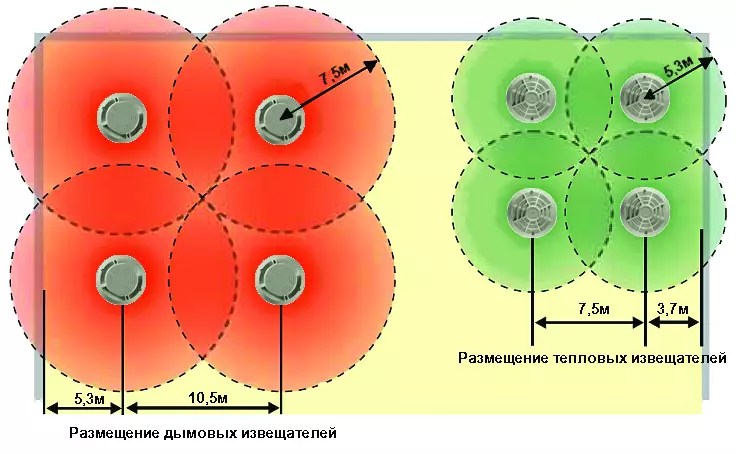
- Installation is carried out according to the principle of arrangement of the "triangular lattice" - this will save space and protect the entire surface.
- When calculating the range of the device, the orientation of the sensitivity zone in the horizontal plane is used. For smoke sensors - 7.5 m, for thermal sensors - 5.3 m.
- The detector, mounted on the base of the suspended structure, must be positioned so that the sensing element is below the ceiling level. For smoke - by 2.5-60 cm, thermal - by 2.5-15 cm.
- The distance from the walls should be at least 0.5 m.
Calculation of the required number of detectors
Before installing smoke sensors, it is necessary to correctly calculate their exact number for specific premises. In this case, it is necessary to take into account the type of devices and the intended connection scheme. It is important to understand that in the legislation of each state, the installation standards will differ.
In the Russian Federation, it is mandatory to install at least 2 sensors per room. The regulations state that it is recommended to install detectors on each section of the ceiling with a width of 0.75 m or more, as well as on elements building structures with a protrusion of 0.4 m.
Thus, a separate zone of the interceiling space should be equipped with:
- three sensors if they are connected to a two-threshold reaction loop or to three separate loops with a single response threshold;
- four detectors when they are connected in pairs to two different loops of devices with one threshold;
- two devices with an alternating operation circuit.
Despite the fact that point sensors are capable of monitoring up to 25 meters of a room, it is imperative to install at least two pieces if they are addressable and at least three if they are analog. This is explained by the fact that the spread of smoke and fire in the ceiling zone has its own characteristics, which means that this area is more difficult to control.
Mounting order
At the beginning of the installation of the device, the required number of sensors and mounting points are first determined, only then the installation process begins.
In false ceiling
In plasterboard suspended ceilings, sensors are most often installed using the tie-in method - the most aesthetic and convenient way. In this case, it is recommended to use heat-resistant cables with an NG type braid, copper conductors and minimum cross section in 0.5 mm. It should be noted that the installation of sensors in blind corners between the wall and the ceiling is strictly prohibited.
Fire sensor mounting diagram:
Step 1. Determining the number of detectors, their approximate location and distance from each other. It should be noted that smoke sensors must be installed both in the suspended structure itself and on it.
Step 2. Fixation of annunciators is allowed only on a frame or concrete floor in an overhead way. It is possible to insert into a suspended ceiling and fasten it with the help of special mounting rings, but in this case the sensor is additionally fixed with a cable to the ceiling.

Step 3. The device is connected only in the absence of power and in accordance with the diagram indicated on the sensor packaging. In conclusion, the accuracy of the connection and the performance of the entire system should be verified several more times.
In a stretch ceiling
AT normative documents the mandatory location of fire detectors in stretch ceilings is not indicated, however, the minimum distance from the walls must be observed. When installing the device, preference should be given to those areas where there will be the greatest coverage of control over the premises, taking into account the range of the sensor.
Installation instructions:
Step 1. Prepare a mortgage structure for a stretch ceiling. To do this, flexible metal hangers are screwed to a flat plate made of plastic or plywood, with the help of which the platform is attached to the concrete floor.
Step 2. Align the mortgage to the level with the future ceiling. Bring the wiring down.

Step 3. Stretch the canvas. Glue a thermal ring at the location of the platform so that the PVC film does not tear, then cut a hole for installing the sensor.

Step 4. Connect the device, check its operation. Screw the sensor to the platform.
Safety Precautions and Possible Installation Problems
Despite the fact that the fire alarm system must be installed by a qualified organization in compliance with all requirements and standards, sometimes apartment owners try to mount the device with their own hands. Self installation fire detectors is possible, but certain safety rules must be observed:
- During installation work, only special ladders or ladders are allowed to be used - any improvised means are strictly prohibited.
- Only specialists with knowledge of the instructions and the specifics of work are allowed to install and maintain the fire safety system.
- Tools used in the process must have insulated handles.
- First you need to measure the voltage between the phases using a portable voltmeter.
- Before installing the system elements, be sure to check the strength of the fire detectors on the false ceiling or tension structure.
Common problems during installation and operation
Problem #1: violation of the operation of one detector when all the others are in good condition.
Remedy: check the installed smoke sensors and, if necessary, dismantle them. In this case, it should be borne in mind that if the voltage indicators are different, then the wiring for fire extinguishing and signaling should be located in separate boxes. With open laying, the distance between cables and other communication systems should not be less than 0.5 m.
Problem #2: No alarm.
Remedy: check the mounting surface, turn the optical indicator of the device towards the main entrance.
Problem #3: Battery failure.
Remedy: if the sensor is installed on the ceiling itself, then changing the power system will be quite easy - you just need to carefully unscrew the device from its platform. When installing the device inside a false ceiling, it will be necessary to partially dismantle the ceiling sheet.
Thus, the main requirement for the installation of a fire detector remains its effective subsequent operation. When choosing a device, it is advisable to give preference to reliable manufacturers, whose models are guaranteed to last for several years.
It is better for the owner of the premises to rely on qualified specialists who are able to calculate the number of detectors and create the correct layout for their location - only when competent installation operation of fire detectors without failures and malfunctions is possible.
During the construction of the building, fire safety is of paramount importance. The lives of people depend on the installation of the necessary sensors. For this reason, alarm sensors are installed in the room. If there is a plasterboard structure on the ceiling, these appliances can be installed on it. In this case, some questions arise: what are the requirements for fire safety? When is the installation of detectors necessary, and when not?
fire system requirements
The fire safety documents indicate that the sensors are defined by the value of the combustible mass of one meter of wiring. They are not installed in those places where there is nothing to burn. But, if they are necessary, there are requirements for them:
- During installation, keep the distance between the base ceiling and the false ceiling, it should be enough to accommodate the wires and sensors.
- Correctly count the number of appliances and combustible materials to ensure full safety.
- Examine carefully ceiling surface to identify the area where the densest location of the cable and other communications. Wiring should be 30 cm apart.
- Determine the linear footage of each brand of cable separately. To do this correctly, refer to a special table with data on combustible substances (measured in liters).
- If the number is less than 1.5 liters, then there is no need to install detectors behind the false ceiling. Otherwise, it is necessary to install a loop, and hence sensors.
Type of sensors
These devices have differences and can be divided according to some parameters. Sources of sensors triggering are heat, smoke and fire.
They differ in the nature of detection.
Dotted are smoke and heat detectors, which control the situation only in the place where they are installed. Used most often.
Linear - these are sensors used less often, they control the increase in temperature or smoke in parts of the linear space of the building.

They are connected to control devices by wired and wireless methods.
Addressable is a signaling system that identifies each individual detector.

Autonomous - these are sensors that are equipped with a sound annunciator and a built-in battery. There is no need to connect it to the device, since use in large buildings makes it difficult to check the operation.

Two-point sensors have recently become known on the market. What are they? These are two devices located in the same housing, but located at a distance of 80 centimeters from each other. One sensor controls the base ceiling, and the second - suspended. From separate loops, both sensors are connected to a 6-pin base. This option simplifies both the dismantling and installation of devices that serve the space between the ceilings.
Smoke detector
Install such devices in places where a fire can be accompanied by a large amount of smoke. It - office rooms, cinemas, clubs and commercial enterprises.
Modern detectors are quite attractive in appearance, they do not spoil the interior. They are mounted using the tie-in method, which helps to use them on plasterboard ceilings.

The grossest violation is the refusal to fix the wiring loops directly to the control devices.
Sensors can work falsely and this is sometimes facilitated by fluorescent lamps. This happens when the norm of the distance of sensors and lamps is not adhered to. The devices also react to the aiming of the ceiling fixation fittings. To avoid this, choose a quality product.
Infrared Linear Sensor
When a fire alarm is needed in large rooms, it is recommended to purchase just this type of sensor, and not a point one. The price is certainly higher, but the equipment of the entire system will cost several times cheaper.

When sensors are not required
- The wires are hidden in corrugated pipes or special steel boxes.
- Cables in insulated tubes.
- The gasket is made with a single-core electrical power supply of the NG type.
- NG-type wiring was used, but which does not contain combustible substances more than 1.5 liters per meter.
Installation of sensors
Where and how many devices to install is written in the recommendations. It is advised to install multipoint. When installing a point sensor behind a suspended structure, keep a distance of at least 0.5 meters from the wall, and 0.1 - 0.3 meters from the ceiling. Laying sensors is prohibited in the corners between the ceiling and walls. The distance from the fixtures should be at least half a meter and they should be positioned so that there is free space around each fixture at a distance of 0.5 meters.
When mounting a wireless device in the absence of ventilation, place them behind the structure in free space, only in the upper part.
Conventional detectors require separate loops for connection in the space between ceilings. Install above the main sensor which is mounted in the ceiling. Provide the sensor itself with a powerful light indicator. Connecting the device provides control of the health and operation of the sensor and the electrical circuit.
Installation instructions
To begin with, the number, place, distance of devices is determined. Sometimes sensors have to be mounted both in the suspended structure and behind it.
Sensors can only be fixed to load-bearing parts: on a frame or concrete floor.

There are two types of sensor gasket: mortise and invoice.
The second method is simpler, but not aesthetically pleasing. To make a tie-in, use special rings or other devices. Please note that the sensors are made of plastic or metal.
On plasterboard ceilings, tie-in installation is more often used, it has a beautiful appearance, and on plastic panels, only this method is used, because the material is too weak for overheads.
Sensor connection diagram
Fire safety standards recommend the use of only fire-resistant and insulated cables that do not spread combustion. Their cores must be copper and with a cross section of at least 0.5 mm. The diagram is located on the packaging with the sensor and on the control unit. They are not complex and are similar to each other. The main thing is to observe the sequence of work and connect the contacts correctly.
Connect the device only when the power is off. After mounting and connecting the circuit, it is better to check once again how correct the connections and the performance of the system are.
Sensor placement
Four detectors are required if they are connected in pairs to different loops having the same threshold.
Two devices, if the connection was made according to a scheme that requires sequential operation of at least two devices and with a guarantee of replacement if necessary.
Two sensors, if they were connected to the circuit, when one device is triggered.
From this it follows that the norms are as follows: behind the ceiling structure in without fail two sensors are mounted if they are address type. The same amount is required if the devices are analog.
If they are analog, but the connection comes from two electrical circuits control devices that have one response threshold.
It is allowed to install one address type sensor in the room if the alarm system does not control the fire extinguishing and guarantees the absence of false alarms.

Security measures
If the supply voltage is different, then the wiring for the fire extinguishing and alarm system is mounted in separate boxes. If laying is performed open way, but there is no protection, then the distance between the wiring and bundles with different voltages should be no less than 0.5 m. Using single-core wires, the distance is halved.
In crowded places, fire safety is monitored more strictly. In places of entertainment or nightclubs and other institutions, there are special requirements to safety.
When installing plasterboard ceilings, you may encounter the same problems. The design must comply with fire safety standards, besides, have an aesthetic appearance and be functional.
The cellular ceiling complies with these standards. It is made of aluminium. This is a material that does not burn and does not contribute to the spread of fire. The design is open, like gratings with different sizes and drawings. Such properties help to install a fire alarm for drywall construction without interfering with the functioning of installed systems.
The cost of suspended ceilings includes ventilation, installation engineering communications, installation of lamps and electric wires.
The requirements that are put forward to the sensor, arranged behind the ceiling, are that nothing prevents it from working at the right time, and those in the room can leave it. For this reason, the material should not be combustible, destroyed by high temperature or flame exposure. A properly installed ceiling mounted fire alarm is effective. Mineral fiber does not catch fire and slows down the fire process, which allows for the evacuation of people. The standard thickness of mineral fiber boards is 1.5 centimeters. They protect from fire from above and below the space between the ceilings and the entire room.
Since the action of these sensors, if installed at home, saves people's lives, they are mounted in apartments and houses. The alarm, which is located behind the false ceiling, warns of smoke or fire. For this reason, you can avoid unpleasant consequences that brings fire. After all, fires often occur at a time when people are sleeping and cannot have time to escape. This leads to the fact that residents get severe poisoning with fumes or smoke, in other cases, a fatal outcome is even possible.
Fire detectors are divided into fire and smoke. They have the same function - to warn of danger.
They differ only in that the smoke alarm is triggered when there is smoke or a source of heat. Such sensors are used most often and their cost is affordable. The fire alarm can be triggered by a single sensor.
At home, it is enough to have one sensor that runs on batteries. Some devices operate on a 120 volt network, and if the electricity is turned off, then they are powered by a battery. The batteries should be changed once a month.
Installation Requirements
These are the points that apply so that later there are no problems and errors.
- The sensor is connected in such a way that after dismantling it does not interfere with the operation of others.
- The surface on which it is installed must not be transferred without the use of a tool. In addition, the device itself should be turned so that the optical indicator looks towards the main entrance to the room.
- The control panel is placed closer to the central entrance. If the object is on round-the-clock duty, an indication and control panel is installed in the room where the guard is located.
- In the building where the main fire safety system is located, other local systems are connected to it to provide signals: "Fault" or "Fire".
How to install detectors, see this video:
