Description of the design. Materials Drawing of a metal staircase dwg
When not one floor, but two or three are planned in a residential building, it is imperative to think through the structure that will lead to the upper tiers. Drawing metal stairs, created based on measurements, will help facilitate the work and make the arrangement process accessible.
Schemes and drawings of metal stairs
The design of a metal staircase has all the necessary safety and durability parameters. That is why they often rely on this type of product. The metal is practically not susceptible to corrosion, effectively emphasizes the style of the room and brings rigor and elegance to the design. Looking at wide variety of the proposed metal stairs, one can understand that even a person who has no experience in such incarnations can make them with his own hands.
 Drawing with dimensions of a metal staircase
 The most important thing is to choose a design that will be feasible to draw, prepare and install in the space of the room or outside it.
Advantages

Flaws
- One of the disadvantages is the bulkiness of the gangway and railings. But thanks to the skills of modern developers, you can easily select a circuit that will best match the load for a particular room.
- Some bends and decorative elements difficult to implement without special skills.
Based on the priorities and shortcomings of the material and design as a whole, you can bet in favor or against such a decision.
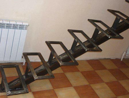
Metal staircase on stringers
It is much easier to make a drawing of a metal staircase if the structure is equipped with the help of stringers. This is due to the fact that you need to calculate the distance for each step and prepare the material that will subsequently be fixed to the base. Stringers are the base (foundation) in the form of a future staircase. 
It can be made from different materials and be secured as required by the premises. Of course, to purchase suitable stringers, measurements are still required.
After all, the design must fit the parameters of the space allocated for the stairs. A ladder on metal stringers will help even inexperienced craftsmen complete the installation task.
The main thing is to correctly mark the place where the gangway will be located. And also have on hand the tools and materials necessary to implement this idea in your own home.
Advantages
 Metal staircase design option
 Due to the fact that gangways equipped with stringers have earned their vocation, positive aspects such a solution is obvious:
- This makes the work process easier;
- Allows you to easily organize the order of actions;
- Such structures are strong and durable;
- Thanks to stringers, even an inexperienced specialist or just a home owner will be able to realize his plans and make them a reality;
- This element allows you to devote more time to details and design experiments that will decorate.
These are not all the positive aspects of staircases on stringers; each owner of a private house finds his own independent advantages.
Flaws
It is necessary to correctly determine the size of the base for the steps so that the structure fits clearly into the interior. It is not difficult to make such calculations. Simply measure the height, angle and width of the required installation.
How to make a drawing of a metal staircase
Make your own drawing of a metal staircase with my own hands simple enough. To do this, you need to take measurements of the space in which the steps leading to the second floor will be located.
Required materials for measuring
In order to measure space, you should have the following accessories on hand:
- Tape measure with maximum length;
- Surface level meter;
- Chalk or a special felt-tip pen that can be used to make the necessary marks on the wall, floor and ceiling.

This is a minimum set of accessories that will help you carry out the measurement process efficiently and quickly.
Required materials for the drawing
To make the diagram as accurate and correct as possible, you should also prepare a number of stationery items. Namely:
- A sharpened pencil or black marker with a thin tip;
- A sheet of paper or whatman paper;
- Ruler;
- Compass.
You should draw the diagram carefully and carefully so that during the actual installation process you do not make errors that are difficult to correct.
What parameters need to be measured
In order not to make a mistake and correctly make a drawing with your own hands, you will need to make the following measurements:

After taking measurements, you can transfer the recorded parameters onto a sheet of paper, forming a diagram of future gangways.
What nuances must be taken into account during the process?
When taking measurements, be sure to pay special attention the following factors:

What types of metal stairs are there?
It can be different, but each of them is worthy and we often choose. The designs of metal stairs are:
| Screw | Such gangways will help preserve maximum usable space in the room. The steps will favorably emphasize the sophistication of the design and add a spark to the overall picture of the interior space. The only thing that can stop you is the difficulty of implementing the drawing yourself. Without special skills, a person cannot cope with the measurements necessary for such complex design. And also immediate process Installing stair structures requires some skill and skill. Knowing all the features spiral staircase, a person will be able to implement the idea of installing such a structure in a gangway. After the implementation of the plan, the interior will immediately sparkle with new colors. |
| Marching | This option is most often used to implement the idea of installing staircase structures. For such an array it is easy to draw a diagram even for those who have never encountered such a task before. Marching stairs can be straight, leading to the second floor or with turns (this helps to save space). Measuring the parameters required for drawing any of these types of gangways is very simple. Enough to have on hand necessary tools and devices. Direct installation of the structure is also elementary. You just have to stick to it step-by-step actions, which can be read about in any thematic literature. |
| Mounted | There are structures leading to the second floor that are supported on the wall. No supports are installed under such structures. The main load-bearing and load-bearing structure is the wall. Therefore, before proceeding, you should make sure that the walls are strong and ready to withstand such a high load. If yes, then you can safely equip a hanging metal staircase. Such a staircase will help save space and make the style of the room elegant. |
When designing the stairs, materials from Series 1.050.9-4.93 were used. The width of flights of stairs is accepted as 1.2 m. The steps are adopted according to STB 1169-99 L=1500mm.
dwg format
Description of design
Stringers are adopted according to Series 1.050.9-4.93, issue 3, wall and front beams - according to Series 1.050.9-4.93, issue 3
Element interface units - according to Series 1.050.9-4.93 issue 0-1.
In the order for steps it must be specified that all main steps LS-12 and LS-15 must have M1 embedded parts for fastening stair railing posts, taking into account the option of stairs with clockwise rise. The landings are designed according to Series 1.050.9-4.93, issue 0-0. BNB 5.03.01-02
The stringers are attached to the platform beams using M16 bolts. After checking the correct position of the mounted structures, the bolt nuts must be secured by welding them to the bolt rod, or by hammering the threads.
Welding is carried out using electrodes E-42 hshv.=6mm according to GOST-5264-80.
Cover the stringers and beams with steel woven mesh 1-R-12-1.6 GOST 8536-80 and plaster them cement-sand mortar M50 25 mm thick.
The beams rest on the rear mounted on a monolithic belt


In order to carry out a competent, correct calculation of the stairs, it is possible to use special program AutoCad, which will greatly help and save time.
Design of a metal staircase with a platform - dwg drawing
The use of specialized design programs significantly saves time in the process of preparing drawing documentation, as well as in calculations. In addition, using the programs, you can be sure that the design is made in accordance with existing building codes and GOST standards.

Thanks to AutoCad, even a beginner can design a metal staircase for any purpose, without any special knowledge of the program. AutoCad systems and equipment include ready-made units for the design of metal staircase structures, industrial and household use, fire escapes, and also contains information about installation and installation.

Based on the given parameters of the building, using AutoCad, you can make a drawing of a metal structure of any configuration, and, importantly, in accordance with fire safety standards.

Components of a staircase structure
The staircase structure will be “built” from ready-made blocks offered by the program, which can be edited by setting the necessary parameters.
A metal staircase consists of several main elements:
- Staircase steps;
- Playground;
- Railing;
- Fencing.
Elements, nodes
In the program, the drawing will be created by compiling and selecting the parameters of each specific element. Thanks to the versatility of such computer software, it is possible to design and calculate in advance absolutely any metal staircase with or without a platform.
The entire drawing will be presented in section so that you can view the selected element more carefully. Each selected and approved element in the drawing is presented not only structurally, but also all the main dimensions of flights of stairs or flights are shown.

The set of finished documentation, made in the AutoCad system, will include not only a longitudinal section of the designed objects, but also a transverse one, as well as a specification with the necessary fasteners and the corresponding GOSTs.
Staircases, staircases
Flights of stairs in the program are carried out in accordance with GOST 9818-85 and can be of the following types:

Flat and ribbed types have one significant difference: some are installed on a slab, while others are installed on a stringer. LMP staircases are larger structures that are joined together by a slab.

For each type of staircase structures, according to the articles included in the program, it is selected landing, for example, marching type or ribbed.
Particular attention must be paid to turning staircase design– it can be made in two versions: right and left.
Series
The AutoCad program has its own data library, which includes regulatory documents and construction rules. Such documentation, on the basis of which drawings are constructed, is called a series. The series of regulations includes not only the basics of constructing a specific metal structure, but also GOST for the material used, fire safety and rules of basic urban planning.

For example, to build metal stairs with a platform, you should take Series 1.450.3-7.94 Metal stairs, platforms, fences as a basis. Issue 2.

There are issues 0-2, which characterize the material used, so issue No. 2 involves the design of structures from hot-rolled profiles.

Documentation - series, regulate the basics of construction and installation of steel stairs, railings for them, and the necessary knowledge for their proper installation and operation, as well as a set of additional elements.
Railings, fences
Railings and railings are used in the construction of stairs, which are installed with floor heights from 3 to 4.5 meters, erected under standard construction conditions.

Also, stair railings are applicable for reconstruction of residential buildings with floor heights of 2.8 meters.

Specialized march fencing is designed taking into account standard sizes buildings of series 1.251.1-4, issue 1 and series 1.252.1-4, issue 1 and stairs of individual steps according to GOST 8717.0-84 and GOST 8717.1-84.

Also products this issue provide fencing for staircase structures at entrances to basements.
Construction of a metal fire escape ladder
Fire escape, unlike standard ones metal structures, is carried out in accordance with certain norms and standards, based on where it will be located:

External stairs are most often lightweight, small-sized structures, the steps and railings of which are made of special reinforcing steel. This is done in order to eliminate possible troubles with accumulated snow in winter time, as well as to facilitate the design. IN mandatory fire escapes installed on the streets must be treated with a special anti-corrosion compound. This is due to the need to extend the service life of the metal structure.

Metal fire escapes installed inside the house are intended mainly to evacuate the population, so the handrails and steps must be as safe and fireproof as possible. For this purpose, a special fire-resistant coating is used.

Requirements for drawings
A drawing made in AutoCad must meet certain standards:
The beginning of construction must begin with the axial and bearing lines that run in the middle of the stairs.
The section of the staircase structure must be made in such a way that all bevels and bends are visible.
The staircase structure must be tied to the walls.
It is necessary to mark (with dimensions) the level line of the floor, ceiling, second floor, attic floor.
Outside the outline of the main drawing, dotted markings of window and door openings are made.
If the drawing is done “for oneself”, for self-made stairs, in the future, such simple basics will be enough to work with the program.
To start building a staircase structure, you need to set the initial parameters:

To the benefits modern technologies significant time savings can be attributed to the execution of drawings, diagrams, plans, as well as the necessary calculations. In addition, the program allows you to see 3D projections, examine all the angles of the staircase structure, its location relative to the space of the room.
Not only professionals, but also beginners can use such a program. Having started to build the stairs yourself, you should resort to the help of computer technology.
Message
sent.
SERIES 1.450.3-7.94, issues 0, 1, 2 in .dwg format
STAIRS, PLATFORS, STEEL STAIRS AND FENCES FOR PRODUCTION BUILDINGS OF INDUSTRIAL ENTERPRISES
Issue 0.
MATERIALS FOR DESIGN
Issue 1.
STRUCTURES FROM COLD-FOLDED PROFILES. KM DRAWINGS
Issue 2.
STRUCTURES FROM HOT-ROLLED PROFILES. KM DRAWINGS
This digitized series matches the original source perfectly.
AutoCad Opener
Developed series 1.450.3-7.94 "Stairs, platforms, stepladders and steel railings for industrial buildings industrial enterprises" consists of the following releases:
issue 0. Materials for design
issue 1. Structures made of cold-formed profiles. KM drawings
issue 2. Structures made of hot-rolled profiles. KM drawings
This issue 0 contains a description of the construction of steel stairs, platforms, stepladders and guardrails for them, necessary information for them correct installation and operation, as well as layout diagrams and nomenclature of stairs, platforms, stepladders, fences and additional elements.
1. PURPOSE AND SCOPE OF APPLICATION
1.1. Steel stairs, platforms, stepladders and fences are designed for use inside and outside heated and unheated buildings of industrial enterprises and engineering structures, erected and operated in areas with snow and wind loads
I... according to SNiP 2.01.07-85, non-seismic and with a calculated seismicity of up to 9 points; with an estimated outside air temperature of minus 65°C and above; with explosion-proof categories of production; with a non-aggressive and weak degree of aggressive environmental influence under normal temperature and humidity conditions according to SNiP II-3-79.
1.2. Stairs, platforms, stepladders and fences can be used as intra-shop ones, incl. for maintenance technological equipment, for arranging landing sites for bridges electric cranes, as external evacuation and fire fighting equipment, with minor modifications for servicing steel tanks up to 18 m high, for servicing vertical and horizontal heated and unheated apparatus and vessels with a diameter of up to 20 m and as bridges for servicing electric lamps.
2. TECHNICAL DATA
2.1. The main parameters of flights of stairs and landings, as well as the maximum permissible loads on them, are taken into account taking into account an overload factor of 1.2 in accordance with the requirements
SNiP II-23-81 and SNiP 2.01.07-85 and are given in table. 1.2 of this explanatory note.
2.2. Layout diagrams of structures and docking units are shown on sheets 1-13 of this document - KS.
2.3. The width of flights of stairs and platforms in accordance with the requirements of SNiP 2.01.02-85 and SNiP 2.09.02-85 are accepted in two sizes: 7OO mm and 900 mm. The angle of inclination of flights of stairs is 45° and 60°.
2.4. It is possible to pierce flights of stairs onto both metal and reinforced concrete platforms and floors.
There are three options for fastening structures into tiers:
I - supporting flights of stairs and landings on load-bearing structures buildings;
II - flat created by flights of stairs and landings vertical farm, pinched at the base and free at the top, is connected with belts-columns and additionally secured with ties in increments of no more than 9 m to the walls of the building. This option can be used for arranging fire escape and escape stairs.
III - a flat vertical truss created by flights of stairs and landings, pinched at the base and along the upper tier, connected by a column-belt. This option is recommended for arranging landing sites for electric overhead cranes.
For options II and III, the rise height of the flights of stairs is assumed to be 3.6 m. The height of the landing marks can be adjusted by changing
the lifting height of the first flight (increase module 0.6 m) and due to the change in height relative to the zero level ±0.3 m.
2.5. When operating stairs, platforms, stepladders and fences in areas with seismicity 7...9 points, it is necessary to provide for: floor-to-floor cutting that does not affect the rigidity of the building frame, the use of anti-seismic joints, the gap between the structures and the walls and the building frame of at least 20 mm.
2.6. The parameters of vertical fire escapes and ladders comply with the requirements of SNiP 2.01.02-85 and are accepted with a width of 700 mm. In the lower tier, the structures rest on the foundation and are connected in height at a distance of no more than 9 m additional elements with the walls of the building.
2.7. The installation option and selection of a set of structures is determined by the designer taking into account the following - all other things being equal:
for buildings made of light metal structures, it is recommended to use stairs, platforms, stepladders and fences made of cold-formed profiles as they are lighter and create less load on the building frame and foundation;
structures made from hot-rolled profiles can be manufactured under construction conditions; structures made from cold-formed profiles are manufactured, as a rule, at specialized enterprises.
3. TECHNICAL REQUIREMENTS
3.1. The material of structures operated in areas with a design temperature of outside air: up to minus 40 °C should be group C235 according to GOST 27771-88, up to minus 65 °C group C255 according to GOST 27771-88.
H.2. The structures must have an anti-corrosion coating in accordance with the requirements of GOST 9.402-80, GOST 9.401-91 and SNiP 2.03.11-85.
3.3. Substitutions of materials in structures are allowed:
To cover the steps of stairs and landings, it is possible to use hot-rolled corrugated steel in accordance with GOST 8568-77 and “Bataisk” type grating in accordance with TU 36-2044-77.
For load-bearing structural elements, it is possible to replace them with rolled products or profiles with similar or higher strength properties.
It is possible to assemble structures from cold-formed and hot-rolled profiles.
3.4. Packaging of structures must ensure the safety of protective decorative covering. Transport packages should weigh no more than 3.5 tons. Structures should be stored on pads in stacks no more than 2 m high. Additional elements are stored in boxes. Storage conditions 7 according to GOST 15150-69.
3.5. During installation and loading and unloading operations, the structures are strapped “to the girth” using protective gaskets to preserve the decorative coating.
4. INSTALLATION
4.1. When developing installation drawings, the design organization must be guided by approximate wiring diagrams, nodes and nomenclature of this release.
4.2. The calculation of foundations for a selected set of structures according to bracing options is carried out by a design organization that uses the structures at a specific construction site.
Structures fastened according to option II (external main evacuation and fire escape stairs) are designed for maximum loads on stairs with a height of 22.2 m, taking into account that:
wind load is transferred to the foundation through flights of stairs;
vertical constant useful and snow load transmitted through support links.
Structures braced according to option III (stairs for landing platforms of overhead electric cranes) are designed for temporary loads
3.0 kN/m² (300 kgf/m²) with a staircase height of 15 m.
The fencing of stairs and platforms is designed for short-term loads, provided for by SNiP 2.01.07-85 and GOST 12.4.059-89.
Vertical fire escapes are designed based on the maximum loads on ladders with a height of 20.1 m (wind load and dead weight).
4.3. The connection of elements of stairs, platforms, stepladders and fences is carried out using bolted joints and mandatory welding of hinge joints.
The formation of a reverse slope of steps of more than 1° is not allowed
when installing stairs.
The fences are assembled on site (taking into account left and right execution). The joining of handrails, strings and curbs to each other is carried out by welding with the fitting of the joint in place.
Fastening the stepladder guards to the stepladder frame and joining the racks is done with bolts.
4.4. Installation features are indicated in the nodes.
4.5. Installation of a set of structures must be carried out in accordance with the requirements of SNiP III-18-75 and taking into account the safety requirements of SNiP III-4-80
5. PRODUCT DESIGNATIONS
5.1. A set of structures, depending on the rolled metal profiles from which it is made, has the following indices in its marking:
X - cold-formed profile;
G - hot-rolled profile.
5.2. Depending on the operating conditions, stair steps and platform decking are made from:
F - steel sheet with rhombic corrugation;
B - expanded metal sheet steel;
R - strips on the edge and round steel (VISP type).
Examples of brand definitions are given in the corresponding nomenclature for stairs, platforms, stepladders, fences, and additional elements.
