We make a homemade pipe bender and profile bender with our own hands. Making a pipe bender with your own hands: design options and features of finished products Pipe bender for profile pipes drawings
Hello. Today I want to tell you about my homemade pipe bender, which I made this winter.
I've been thinking about building a machine like this for a long time. With its help, you can roll profile pipes, giving them an arc shape. This operation is in great demand - you can assemble, for example, a greenhouse, a canopy, a canopy over the entrance. You can give an interesting shape to the top edge of a gate or metal fence...
And this winter I found time and started doing this homemade project. When designing, I considered the following points:
Considering that I am not going to use it professionally, I decided to make a relatively lightweight design that is also easy to transport and will not take up much space when stored. (After all, I will bend pipes either near the house or at the dacha. I will not use it every year. And I certainly won’t have to bend large-section pipes). Therefore, I decided not to make a powerful stationary structure with a long service life...
There are many descriptions of similar machines on the Internet. Their operating principle is the same - they are based on three shafts, one of which is movable in a vertical plane. It is he who bends the pipe and, rolling along these shafts, it takes the shape of an arc.
... Basically, they are all divided into two types:
1. With a “breaking” frame:

2. With a movable central carriage.

The second type is more compact (albeit more complex), so I decided to do just that.
In turn, pipe benders with a movable central carriage are also divided into two types: With a driving central shaft and with two driving outer shafts connected to each other by a drive chain.
If you make the central shaft leading, then it is possible to easily change the distance between the outer ones, which will provide additional adjustment of the work depending on the cross-section (and therefore rigidity) of various profile pipes.
At first I doubted whether there would be slippage if only one drive shaft was used, but after observing a pipe bender with one drive shaft in operation, I realized that for not very large sections this force was quite enough. But I’m not going to bend pipes with a height greater than, for example, 60 mm... That’s why I settled on such a device.
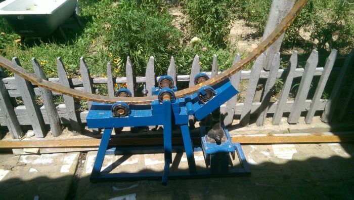
And after some time, I got a pipe bender, which you will see in this video:
So, in more detail... I needed:
1. Old faulty hydraulic jack
2. Profile pipes of various sections.
3. Circle with a diameter of 40 mm, a length of 500 mm.
4. Bearings 6206 4pcs
5. Bearings 6202 8 pcs.
6. Channel No. 65
7. Thrust bearings 2 pcs.
8. Hardware (bolts, nuts, washers, cotter pins)
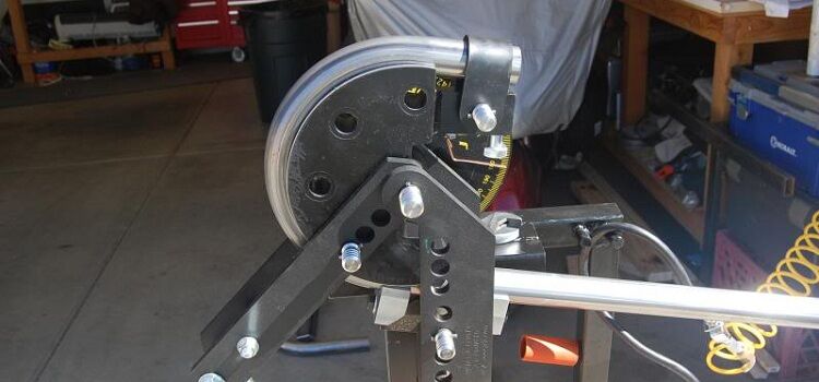
I started by making the main working elements - shafts. I had a 40 mm round timber, half a meter long. It was possible to take a thicker one, but... I had this one!))). Therefore, I sawed it into three parts. Two - 130 mm each, and one - all that remains))))). On lathe machined shafts for bearings (up to 30 mm diameter)

The shafts are ready. I started assembling the carriage. I decided to make it from the 65th channel - the 206th bearings fit well into it...


After I cut the channel to the required length, I drilled a hole in its center and welded it across the sides along the corner:


After that I started making the center screw. I took it from an old hydraulic jack that I found on scrap metal. When I was sure that it would never be a jack again, I decided to use it.

The screw itself had a diameter of 30 mm. I drilled through its end with an 8mm drill blind hole, hammered a pin in there and grabbed it with welding:


The screw in the jack was screwed into the piston. I cut off the top part (with thread) and another ring, 20 mm wide.

I put this ring on the screw, inserted the screw itself with a pin into the hole in the carriage and welded the ring to the carriage:


This will be the seat for the support shim. (I selected it according to the outer diameter)

I screwed a nut onto the stud and drilled a hole in the nut and in the stud:


It was only possible in high heels, but it seemed safer to me. The nut can now be secured with a cotter pin after assembling the unit. And the assembly, as you guessed, consists of a screw, a bearing, a carriage, a second bearing and a nut.


Now, when pressed, the screw will rest against the carriage through the upper bearing, and when lifted, the carriage will hang on it through the lower one.
On the sides of the carriage I welded a piece of trim profile pipe 50 by 20 - these will be the guides, and in the corners I drilled holes and cut M6 threads. The bolts securing the drive shaft clamps will be screwed into them.


I cut out the bearing mounting clamps themselves from tin - there is no need for strength there, as long as the shaft does not fall when the carriage is lifted:


Next I started making the top plate. It needs to be made very strong - it will bear all the force of the screw when it bends the pipe. Therefore, I made it from the same 65 channel. Since for the vertical racks I decided to use a 50 by 25 profile pipe (the distance between the flanges of the 65th channel is exactly 50 mm. The racks will fit into it and are secured with M10 bolts and nuts), then the width of the top plate should be 50 mm larger carriage width (2 times 25). I cut two such pieces of channel.

Another one was cut into half and spread lengthwise:


I inserted the threaded part cut from the jack piston into the center:

I cooked everything and trimmed off the excess:


Next, I started making the frame. It was also assembled from a profile pipe. I took the cross section 60 by 30:


I decided to make three positions for each shaft. I also made the mountings for the bearings from a profile pipe, so I cut 12 identical pieces of 50 mm each. (Here, and not only here, mine, which I told you about in a previous publication, helped me a lot):

After which I welded vertical posts and bearing mountings to the frame:

And also four “ears” along the edges. Holes will later be drilled in them for attaching the pipe bender with screws to the workbench.


The main part is ready. You can start pre-assembly:

I welded a piece of 20 by 20 pipe to the screw on top. I left it long. I decided that during the testing process, if it gets in the way, I will cut it off and use a removable lever made of a 15 by 15 pipe, which is inserted inside... But, looking ahead, I will say that this was not required. The lever really interferes with turning the drive handle if it is turned a quarter turn (it sticks out across the pipe bender). But it turned out that tightening the screw at half-turn intervals is quite normal.


Next, I started making the drive handle...I decided to make the handle itself from a 15 by 15 profile pipe and a stud. I drilled a hole at the end, inserted a piece of M14 stud into it, welded it and cleaned it:


Now you need to make a bend on the lever itself - the pipe bender will be installed on the edge of a table or workbench.


Next, connect it to the shaft. I decided in advance to make it not only removable, but also so that it would turn over and in the transport position would not dangle or cling. I made this profile on the shaft:


Then I drilled a blind hole and cut an M8 thread in it. The handle will be placed on the shaft and secured through a washer with a wing bolt.

Now we need to make a hub on the handle. I used corner scraps:


Then, like a sculptor, I cut off everything unnecessary :)))))


The lever is ready. On the handle itself (which I have made from an M14 pin), I simply put a piece of polyethylene water pipe and tightened the cap nut.
In general, I would like to dwell separately on my use of cap nuts. I often use them if I need an axis of rotation. Having chosen the correct length of the axle, you can screw on the cap nut and tighten it with maximum force - it will rest against the axle with the cap and will not unscrew easily. Of course, it is not worth fixing the axle on which, for example, a wheel is located, in this way, without a cotter pin, but for “unimportant” axles, such as “curtains” on which something opens and closes, this is quite suitable.
Let's return to the pipe bender... As I already said, such a moment as a very simple reinstallation of the shafts was important to me. (Because, knowing, for example, myself, I am sure that I will not use the option until the last minute if it is difficult to use... For example, if the shafts were close, and a pipe came across with a large cross-section, I would try carefully roll it in this position of the shafts, if to change it you would have to unscrew a lot of nuts... And most likely, it would crush...). That is why I made the bearing mounting points from a profile pipe. The shaft is simply inserted into the desired pair of racks.
But this design contradicted my other requirement - mobility! After all, when moving the machine, the shafts would have to be removed and moved separately... At the same time, the bearings would have to be removed from them (I machined them for a loose fit and they can fall off). This didn't suit me. Therefore, I decided to make a part that would press the bearings from above and fix them. I took two sections of profile pipe, section 50 by 20 mm, wall 2 mm.

After which I cut them lengthwise along the wide part, dividing the wall into 10 and 40 mm. At the same time, on the other hand, I marked this size in a mirror way. I ended up with four blanks like this:

Considering that the width of the 206th bearing is 15 mm, it fits quite tightly inside this workpiece.
I measured the required length, I cut the rest like this:

After which, the upper part was bent down 90 degrees, making a corresponding angle:

I cut out this “tooth” on them:

Now I installed both shafts on one side of the pipe bender, put the resulting parts on them, drilled through them to the vertical posts, and attached them with long M4 screws with cap nuts (the result was axles). In front, I bent the strips of side walls sticking out towards each other towards each other. Now, if we rivet them together, we will get a U-shaped cover, which, when lowered down, will cover the shaft bearings and fix them tightly:
The need to bend profile pipes in the household arises quite often, whether it is preparing blanks for construction metal frame greenhouses or canopies or the manufacture of pipeline parts of complex configurations. Devices are often used for this industrial production, however, purchased products are not a cheap pleasure. It is much more profitable to make a pipe bender with your own hands, especially since the manufacture of the unit does not require any scarce parts, and its design can be repeated in any garage. Homemade device will allow you to obtain a pipe with the desired radius of curvature and at the same time avoid deformations and creases on its surface.
Purpose and types
A pipe bender is an indispensable device when you need to delicately and accurately bend a round or profile metal pipe
The bending of metal profile pipes is directly related to their diameter, wall thickness and material of manufacture, therefore metal manufacturers always indicate the minimum radius of deformation in special tables.
Calculation table for bending radii of steel pipes depending on diameter and wall thickness
It is not easy to bend a hollow pipe without creases and deformations. At home, to do this, it is filled with sand, heated until reddened with a gas burner or blowtorch, and then bent “by eye.” Of course, this method, although labor intensive, is not ideal due to low quality and low accuracy.
Special devices - pipe benders - allow you to obtain a bend of the required curvature without damaging the part. Depending on the length of the fragment that needs to be bent, two types of devices are used:
- lever pipe benders;
- rolling units.
The most common products are lever-type pipe benders. In such devices, the force is applied in the right place, and the bend itself follows the shape of the segment (template), which in some devices can be removable. As a rule, such units include several segments for pipes of various diameters. In addition to segmental devices, the industry produces mandrel and crossbow pipe benders, the bending shape of which is set by two guide rollers and a pressure template (mandrel). This design allows cold processing of round steel pipes in short areas. By the way, compact crossbow pipe benders are the most popular tool among utility installers.
Simple, fast and high quality - these are the advantages of crossbow pipe benders that attract professional installers
Depending on the design of the lever bending device, it can have any type of drive:
- hydraulic;
- pneumatic;
- electric.
Often the operating principle of the unit involves heating the pipe (externally, or with the help of heated air passed inside the rolled product), thereby increasing its ductility, and, accordingly, the quality of the bent section.
If it is necessary to obtain a bend of a large radius, rolling devices are used. Their design includes two guides and one pressing shaft (rollers). The pipe is pulled between the moving elements, setting the degree of bending by the force of the pressure roller. If it is necessary to obtain a large radius of curvature of the workpiece, the procedure is repeated.
Rolling attachments may have an electrical drive for the guide shafts, as well as a hydraulic, mechanical or pneumatic drive for the pressure roller.
Designs of homemade devices
The simplest option available to most novice craftsmen is bending pipes according to a pre-made template. This method is used when it is necessary to obtain a large number of blanks of the same type.
Bending a pipe according to a wooden template is the easiest way to solve the problem
As a template, you can use a structure made of wooden boards. The thickness of the wood is chosen based on the diameter of the pipes being bent - the board should have a margin of 2–3 cm. To prevent the metal profile from sliding off the template during work, the ends are processed with a slight slope.
The structure is attached to the floor or other surface in any way, installing a stop for the pipe nearby. Having inserted the profile into the gap between the template and the thrust element, smoothly and carefully press on its other end, pressing the pipe against the template. To ease the pressing force, you can use a lever of a suitable size or install a winch.
A winch can facilitate the process of bending pipes using a template
In a similar way, you can bend a metal profile of small diameter. If it is necessary to change the configuration of a pipe larger than 1 inch, then the template is made from sections of powerful fittings. To do this, holes are made in the concrete slab along the required trajectory, into which guides are inserted in the form of pins from sections of pipes, fittings, etc. The bending is performed by securing the edge of the metal profile by welding.
The advantage of this method is its cheapness and simplicity, however, the accuracy of the resulting blanks and the quality of their processing leave much to be desired. In addition, the template will have to be made every time you need to obtain a bend of a different radius.
Factory-made snail pipe bender
For making large quantity For similar workpieces with a small radius of curvature, you can use a snail pipe bender. This unit consists of two pulleys (wheels) of different diameters, mounted on shafts. Having fixed the end of the pipe on the impeller, use a roller of a smaller diameter (drive wheel) to press the workpiece, simultaneously rolling it along the workpiece. As a result, the pipe bends around the surface of the large pulley, repeating its shape. The only drawback of this method is the impossibility of obtaining large radius curves.
The most versatile and practical are homemade rolling pipe benders (bending machines), in which you can set any angle of deformation of rolled metal. The simplest design of a rolling unit is a base with drive shafts fixed at a certain distance from each other. Pressure on the pipe is carried out by a movable roller, and it is drawn through the rotation of the drive shafts. Screw devices, jacks, winches and electric motors are used as power drives for such devices. The rolling machine is the most difficult to replicate at home because it requires lathes and welding work. However, there are many variations of its design made by amateurs, which indicates the high popularity of this solution. With the help of such a device, bending of any configuration is obtained, and the process itself is often automated. The only thing such a device cannot cope with is obtaining a minimum radius of curvature of a metal profile over a small segment.
Video: Homemade rolling bending machine
Making a pipe bender with your own hands
To make a pipe bender, you can use drawings of finished structures. After looking at several options and balancing the complexity of the units with your capabilities and the availability of the necessary parts and materials, you can choose the most optimal scheme. For your consideration, we present two models of pipe benders for self-assembly- a manual unit for small pipes and a semi-automatic bending machine.
Manual snail pipe bender for small radii
To correctly bend a profile pipe, you need to have a good understanding of the physics of the process. Manual pipe benders most often use a circular bending method, which avoids the risks associated with bends, cracks and other damage to pipes. To bend rolled metal in such a unit, it is enough to secure the workpiece in the device and press the lever. Bending occurs when a roller is rolled along the pipe, pressing the part to the main wheel.
Materials and tools
To make a manual pipe bender you will need:
- metal sheet with a thickness of at least 6 mm;
- impeller;
- pressure roller
- steel corners 50x50x2.5 mm;
- a piece of thick-walled pipe Ø25 mm;
- axes of rotation (sleeve or bearing assembly);
- a piece of square rod 20x20x40 mm;
- nuts and washers;
- angle grinder;
- welding machine;
- hammer;
- measuring tool.
While working, do not forget about safety precautions. This is especially true when working with cutting and welding equipment.
Pipe bender calculation and drawing
Before you start work, you need to decide what bending radius of profile pipes will be most in demand. Depending on this, the size of the impeller is selected. It is this value that will correspond to the internal radius of the resulting elbow.
Snail pipe bender assembly
The drawing is designed for profile pipes with a diameter of up to 1 inch. The bending radius that can be obtained with this pipe bender is 125 mm (half the diameter of the impeller). If you need a bending unit with other parameters, use the method for calculating the dimensions of a pipe bender.
The main size of the pipe bender fork is the distance between the axes of the impeller and the roller (indicated by the letter a=200mm). In our case, the center distance was selected taking into account the maximum size of the processed profile pipe d = 25 mm, however, it is advisable to add a couple of millimeters to this value “in reserve.”
The center-to-center distance can be determined by the formula a = d + r1 + r2 + 2, where d is the diameter of the profile pipe, and r1, r2 are the radii of the impeller and roller, respectively.
If a roller and a wheel with a groove (some kind of rivulet pulley) are installed in the design of the bending device, then the measurement is carried out starting from the lowest point of this part.
Snail pipe bender fork
To determine the size of the fork, the gap between the roller and its base is taken equal to 10 mm, and a 30 mm margin is also added for attaching the impeller axis.
Fork length c = a + r1 + 10 + 30 (mm).
To determine the internal clearance between the fork side flanges (b), add 1 - 2 mm to the wheel thickness.
You can make the pipe bender more versatile by drilling several holes in the side surfaces of the fork. By rearranging the roller axis, the distance between the working surfaces of the rotating parts is changed.
Step-by-step instructions for making a manual pipe bender
The drawing of the manual bending unit shows that it consists of several main parts:
- base in the form of a thick metal plate;
- impeller;
- video clip;
- fork.
Our instructions will help you perform the work consistently, avoiding errors and inaccuracies.
- Make an impeller and roller. Of course, having a lathe in your workshop will be a huge plus, but even if you do not have such equipment, these parts are not a problem. Any turner can turn pulleys at a very reasonable cost.
When manufacturing moving elements, you should not save. Be sure to make a groove in them for a pipe of maximum diameter, and also carve a seat in the roller for any suitable rolling bearing. If there is a need to change the configuration of the elbow surface, the groove of the impeller or roller is made shaped. When rolling, the roller will leave the required imprint on the outer surface of the knee, and the wheel on the inner surface. To make the turner’s task easier and further reduce the cost of the device, instead of a roller, you can install a pair of ball bearings of a suitable size.Pipe bender impellers can be manufactured with a trough of any configuration
The image clearly shows the ball bearings installed instead of the roller
- On the same machine it is necessary to make axles for the impeller and roller. The thickness of the parts is taken equal to the inner diameter of the selected bearing. The length of the axle for the roller is equal to the width of the fork along the outer dimensions. The axis of rotation of the impeller will be slightly longer, since you will also have to take into account the thickness of the base plate of the pipe bender. By refusing to install bearings, the design can be significantly simplified. In this case, long bolts with nuts can be used as axles. However, it should be understood that bending pipes with this device will be more difficult.
To make a fork you will need metal with a thickness of at least 6 mm
- The side surfaces and rear wall (base) of the fork, as well as a piece of thick-walled pipe as a lever, are cut out of sheet metal.
- According to the drawings, holes are drilled in the fork for the axles of the wheel and roller.
- Weld the fork parts. Special attention should be given to all right angles of this structural element.
Attaching the lever to the fork end-to-end will be unreliable due to the large force applied. It is best to make a hole in its back wall into which the edge of the pipe will fit. By scalding this joint by welding, the most durable joint is obtained.
- Using a grinder, cut out the base (frame) of the device and drill a hole in it for the stationary axis of the impeller.
- If necessary, a bearing is pressed into the roller.
- The roller is inserted into the fork and then secured with welding or nuts.
Snail pipe bender fork assembly
- The fork assembly is installed on the base, securing the impeller axis in the same way as when installing the roller.
- Weld the section square section as a clamp for the pipe being processed.
Holes are drilled in the corners of the base of the pipe bender to attach the device to the workbench. In order for the device to be not only functional, but also aesthetic, during the work process, be sure to clean the weld joints and use a grinding wheel to process the sharp edges of the workpieces. To protect against rust, the finished product is painted with enamel.
Bending machine for profile pipes
Bending long profile pipes requires not only force to deform them, but also a mechanism to pull the parts to the required distance. Often, the design of homemade bending machines uses not a screw, but a jack or winch, and the drive includes an electric motor.
Drawings of homemade devices
Bending machine. Side view Pipe bender with top roller drive Pipe bender with variable distance between rollers
The simplest broaching type pipe bender
In the bending machines shown in the drawings, a threaded drive is used to press the roller. In our design we will use a hydraulic jack, as well as a manual drive using parts from the gas distribution mechanism of automobile internal combustion engines.
Tools and materials
To get started, prepare the following parts and materials:
- corners for the machine bed;
- round or profile pipes for the frame;
- working and broaching shafts (rollers);
- jack;
- springs;
- chain transmission;
- tensioner;
- bearing supports assembled with bearings;
- pen;
- channel for fastening;
- bolts and nuts.
For work you will need hand and electric plumbing tools:
- angle grinder (grinder);
- welding machine;
- electric drill and set of metal drills;
- hammer;
- set of wrenches;
- measuring tool.
Do not neglect personal safety measures. When working with an angle grinder, be sure to use a protective shield or goggles, and carry out welding processes in thick overalls and special gloves. It should be remembered that it is prohibited to work without a welding helmet and carry out electrical installation work on a wet surface or in the rain.
Instructions for making a bending machine
Dividing the pipe bender manufacturing process into several stages will help organize the work more clearly.
- Make broaching (support, drive) and pressure (working) shafts. If you do not have the skills to operate a lathe, you will have to contact a specialist. Be sure to remind the turner to machine the rollers with shanks for installing the sprockets. It's best if you take these parts with you.
The design of the operating shafts must provide for the possibility of installing drive sprockets
Any sprockets and chain can be used. For example, from the gas distribution mechanism of passenger car engines.
- Attach the bearing supports to the shafts and install the drive gears on the keys.
The design of the machine can use drive sprockets and bearing supports from automotive equipment
- Make with welding machine bending machine frame. To do this, first make a square frame with support legs, and then mount a structure on it, along which the plate with a pressure roller will move.
Making a bending machine bed
- A steel U or H-shaped channel is used as a plate. To install the pressure shaft, holes are drilled along the edges of the plate along connecting dimensions bearing supports.
Making a frame for installing a base plate
- A section of channel with a roller is suspended from the top of the frame on four springs, for which nuts are welded at the corners of the plate and frame as mounting loops. After this, a hydraulic jack is installed.

It is necessary to pay attention to the mechanisms discussed in this article. To make a pipe bender for a profile pipe with your own hands, study the detailed instructions, videos, photos, drawings. Using these materials, it is not difficult to implement the corresponding project.
Read in the article
Do-it-yourself pipe bender for a profile pipe: basic data
Before studying the working documentation and installation operation algorithms, you should accurately determine the intended purpose of the product. A pipe bender for a profile pipe with your own hands must be designed for certain forces, workpiece sizes, and materials. It is easier to establish meaningful criteria after familiarizing yourself with the parameters of devices tested in practice.
What are these devices for?

To create the necessary force, a lever mechanism is installed here. A metal pin is used to fix the free section of the pipe. It is installed in suitable grooves of the “comb” before performing work operations.

Using this factory sample as an example, it is easier to study the design features:
- Handle (1) regulates the automatic stroke of the piston in the opposite direction. This solution reduces the burden on the user.
- A hydraulic system is installed inside the housing. When the handle is moved up and down, a force of up to 150 kN is transmitted to the working piston (8). This is quite enough for quickly bending workpieces made of durable metals.
- The support rollers (3, 4) are installed in the required holes of the open frame (5, 9). They do not damage the surface, but provide reliable fixation.
- This removable segment (6) is designed to be bent at an angle of 90°. But with the appropriate configuration, it can be installed on a similar product of a different shape.
- The robust housing (10) is mounted on three supports (7). Rubber pads prevent movement during work operations.
- In addition to cleaning from dirt, you should occasionally check the condition oil filter(11). No other regulatory procedures are needed.


In this technique, a workpiece of the desired shape is used. The pipe is pressed against it using a rotating roller and lever.


Important! Before bending a workpiece using a certain radius, you should study specialized reference books. They provide data on the permissible deformations of pipes made of different materials, with different wall thicknesses. If these instructions are violated, visible or hidden defects will form in the finished products.
Relatively small mechanical loads on working tools are created by levers and manual force. To work with durable metals The equipment is equipped with hydraulics.


Making a pipe bender with your own hands for a profile pipe: drawings and other preparatory operations
A simple device for bending aluminum and plastic blanks is shown in this figure.

To make such a structure you need a strong one. After marking, a round profile is cut out of it. The remaining part is used to make the supporting element. The created parts are rigidly attached to the supporting surface. To ensure the strength of the connections, in addition to screws, clamps are used. Next, the pipe is bent by hand until the desired shape is formed.
Before creating this simple pipe bender for a profile pipe with your own hands, it is recommended to make a basic drawing with dimensions. A template made of thick paper or cardboard on which the markings will be applied will come in handy. It is clear that to produce more complex structures it is necessary to prepare complete design documentation.


It is not necessary to strictly adhere to engineering standards in order to make a pipe bender for a profile pipe with your own hands; a schematic image is quite enough. You just need to indicate all the dimensions, decide on the materials, technological process and components. The project will help solve several practical problems:
- During the preparation process, it will become clear whether it is necessary to use other special equipment.
- A complete list of necessary components will be needed for targeted visits to certain stores.
- We must not forget that the machine must be protected from adverse external influences using wood impregnation, .
- Some parts will be too difficult to make yourself. Appropriate orders should be placed in specialized workshops.
Important! When bending strong metal pipes it takes a lot of effort. In order not to take unnecessary risks, you can use drawings of a proven design, or copies of an industrial design.
Making a manual homemade pipe bender for a profile pipe with your own hands: video and detailed instructions
Here we talk about how to quickly create a pipe bender with your own hands for a profile pipe (video).
The master used available materials, a channel, and part of the drive from an old bicycle. But he had to create the connections himself to ensure the integrity of the heavy structure.
To find out how to make a pipe bender for a profile pipe with your own hands, the drawings and videos are supplemented with descriptions of work operations. Below are the algorithms for several assembly technologies.
Rolling pipe bender
| Drawing | Actions |
 | To create a high-quality one, you can use this drawing as a sample. Here the workpiece is placed between three rollers. The extreme ones (2) – perform supporting functions. To install them at different distances (to obtain the required bending angles), grooves are made in the support strips (1). The necessary pressure is created using a screw mechanism (6, 7). The force is transmitted through the central roller (4), which is rotated by the handle (5). |
 | The holes in the lower parts are created according to these dimensions. A channel with a wall thickness of 4 mm was selected for the workpiece. |
 | The upper part is created with cutouts. They must be made level so as not to interfere with the movement of the support screws. |
 | The thread is cut in accordance with this pattern. |
 | For the handle, you can choose a finished product, or use these sizes. |
 | Once assembled, you will get such a cute and functional product. There are no welded joints. But the components are difficult to make on your own without professional skills and specialized machines. |
Hydraulic pipe bender
The screw mechanism performs its functions too slowly.

This design uses a standard jack. It is fixed rigidly to a bar, which is suspended on two springs. This solution simplifies manipulations with a heavy jack when installing workpieces and clamping segments.
The pipe rests on two round pins. They can be rearranged into other holes to create products with the desired radius of curvature. Parts of a durable steel frame (4-5 mm) are fastened with bolted and welded connections. The design turned out to be collapsible. If necessary, it is not difficult to dismantle it. The jack can be used for other operations.
Holes are created at the base of the frame. Through them the machine can be firmly attached to wooden floor nails, screws. This gives additional stability stationary structure. Its metal parts are degreased, coated and painted. Besides the good appearance good protection against destructive processes is provided.
For your information! When creating a homemade pipe bender for a round pipe, rollers, stencils and segments with a different shape of contact surfaces are used. The technologies used are the same as for bending profile products. The above drawings with appropriate modifications will be useful.
Article
When performing various works with pipes, it is often necessary to bend them in a certain shape to solve certain problems. This is done using a specialized mechanical unit - a pipe bender. Next, we will look at how to make a manual pipe bender for a round profile pipe with your own hands; photos, videos and drawings will simplify the task and help you avoid mistakes.
One type of simple pipe bender
Of course, you can always buy an industrial version. But such equipment is quite difficult to use, and in terms of cost it cannot be called the most affordable. Therefore, as a rule, it is much more expedient to make a manual pipe bender for a profile pipe with your own hands; drawings and dimensions are presented below, so you should not have any difficulties. Various available tools will be useful for production. Such a tool is quite economical in terms of production and very functional.
So, we make the simplest pipe bender for a profile pipe with our own hands.
As a rule, in domestic or garage conditions, front-configuration equipment is made, structurally consisting of the following components:
- 3 steel rollers;
- drive chains;
- rotational axes;
- the mechanism that activates the components of the finished system;
- steel profiles required for the construction of the main structural parts.
Before you start making a pipe bender with your own hands for a profile pipe, study photos, videos, diagrams and drawings. You should be extremely careful when selecting and working (and especially their modification or adaptation) with drawings, since it is extremely important to achieve high accuracy and correctness of the design from an engineering point of view. You can use drawings from different models pipe benders But it’s better to take a simpler one, the optimal solution is a front-type machine.

Diagram of a simple pipe bender
Often, pipe benders are made with their own hands using wooden or polyurethane rollers. This decision should be approached carefully, since these materials are not always able to withstand the loads you need. It is necessary to build on the strength properties of corrugated pipes.
To build a pipe bender for a profile at home with your own hands, you need drawings of a model that suits you. Below is one of the varieties of this drawing, which you can use to produce this type of equipment:

Drawing of one of the bending machine models
To understand how to properly make a pipe bender with your own hands, watch the video, drawings and description of the operating technology. It is very important to understand the technological side of the process. Typically, such equipment operates on the principle of rolling or rolling, thereby minimizing the likelihood of fracture and damage to the pipe.
The pipe is placed between the installation shafts, after which the handle is turned. The technology is extremely simple, but it makes it possible to bend products according to clearly defined parameters and, as a result, obtain the ideal part for solving the task.

Bending system based on a jack
Everything you need to build a pipe bender for a profile pipe with your own hands in a garage using available funds - dimensions, drawings and photos can be downloaded in this material. We also recommend that you watch a video on YouTube about a pipe bender with your own hands, this will allow you to clearly see the entire manufacturing process and evaluate possible difficulties in a specific case.
To create this tool you will need the following components:
- simple jack;
- profiles and a shelf made of durable steel (the frame will be constructed from them);
- very strong springs;
- 3 shafts;
- drive chain;
- other components (bolts and other small parts).

Variation of profile bending on a jack
We make a pipe bender for a professional pipe with our own hands (photos, drawings, pictures)
Build something like this mechanical system quite simple, but it is extremely important to adhere to a clear sequence of actions and accuracy. Everything must strictly comply with the drawings, otherwise the tool will bend the profile incorrectly. To build a pipe bender for a profile pipe with your own hands, you need pictures and drawings, which you can download for free in this material.
The entire production process is divided into several key stages:
- Preparing a reliable frame. Bolts and welding should be used to connect components.
- Installation of the rotation axis and rollers. One shaft is installed below the other two. The distance between the axes of the shafts is determined by the bending angle of the pipe. At this stage, it is important to install the elements strictly according to the drawing.
- The mechanical part is driven by a chain-type transmission. Its design should have 3 gears. It is not necessary to use a new chain; you can take an old one from any equipment.
- A handle is installed on one of the shafts, making it quite easy to rotate it with light movements without much effort. The handle is one of the key components of the mechanism for generating the required torque.

How to make a horizontal pipe bender for a profile pipe with your own hands - video and instructions
There is nothing complicated in the procedure for constructing such equipment; the main thing is to follow simple rules and drawings.
The manufacturing process involves performing the following sequence of actions:
- Install the rings, gears and bearings onto the pressure shaft. Connections are made using a keyway method. Initially, it is necessary to draw all the named elements, then turn them on a lathe. The design will have 3 shafts (2 on the sides and 1 suspended on a spring).
- Make holes in the rings to create grooves and threads.
- Make a shelf (for the production of this part a channel is used, preferably strong and massive). In the latter, also make holes and cut threads to make it possible to install the pressure shaft.
- Assemble components into a single system. To connect, use bolts and a welding machine. First, assemble the frame, which also serves as the legs of the unit.
- Hang the shelf with the pressure shaft fixed on it. At this point you will need good springs. Install the support shafts on the sides. A handle should be installed on one of the latter.
- At the final stage, the jack is installed on the equipment.
For a better understanding of the process, watch how a homemade pipe bender is made from a jack for a profile pipe with your own hands - video on YouTube:
From the above we conclude that making a rolling pipe bender with your own hands from scrap materials is quite simple.
But, the manufacturing process is characterized certain subtleties that should be taken into account:
- the pressure shaft attached by means of keys must also be screwed to the shelf;
- in the process of fixing the pressure shaft, perform the actions in the following sequence: before mounting the shaft to the shelf, it is necessary to weld nuts to it, to which the springs will cling; upon completion of installation, you need to turn the shelf over and hang it using springs of suitable strength;
- A magnetic corner that functions as a holder is perfect for tensioning the chain;
- the stars are twisted using dowels (to make the latter, use a Grover);
- provide a scrolling tube on the drive handle, this will make working much more convenient and easier;
- The installation of the jack must be carried out on a suspended platform (to make all connections, we again use ordinary bolts or a welding machine where necessary).
Making a hydraulic pipe bender for a profile pipe with your own hands (drawings and video)
This page contains all the required information, after studying which you can build a simple pipe bender with a jack with your own hands (drawings, photos, videos and instructions). Many craftsmen, especially at the professional level, build a unit equipped with a hydraulic drive, as this increases functionality. But, producing such equipment is somewhat more difficult in comparison with the option discussed above. This is a rather labor-intensive process. Therefore, we recommend that you watch a video that demonstrates in detail the manufacturing process of this device.
How to assemble a universal pipe bender with your own hands - watch the video:
Based on the design and drawing of this unit, we highlight the components included in its design:
- hydraulic jack (must be designed for loads weighing over 5 tons);
- shoe;
- 2-3 videos;
- durable steel channel;
- thick steel plates and other elements.
To achieve the required bending parameters of the product on such homemade machine, it should be placed in the shoe, secured on both sides. Then a jack is used, the lifting rod of which exerts pressure on the shaft. The latter, in turn, directly influences the fixed product, gradually performing the required bending. When the pipe is bent according to the pre- established characteristics, it can be dismantled. To do this, it is enough to turn the jacking mechanism back a little to relax the entire system.

Painted pipe bending machine

Shafts for the mechanism

Bearings with gears

Profile bending frame

Press roller

Movable platform of the clamp shaft

Shaft fixation

Drive chain with tensioner

Assembled machine
How to make a simple mini pipe bender for fittings at home with your own hands - step-by-step instructions:
- Based on photographs or drawings, make a structure suitable for fixing the shoe, shafts and frame of the future system.
- Fix the steel plate on the bottom platform where the jack will be mounted. Secure everything with bolts and install the drive handle.
- It is extremely important to select the appropriate rollers for the pipe. It is necessary to ensure a tight grip of the product. If you can’t find ready-made ones, you can make homemade ones. The shoe is installed under the rollers. The location of the latter relative to each other is established based on the bending radius required in a particular case.
- To secure the shafts with the shoe, make bolted connections. The drawing below contains all the hole parameters.

Variation of the pipe bender drawing
Technological aspects of the bending process
By following simple tips, you will avoid problems and mistakes during the bending process. Hydraulic units allow you to bend corrugated pipe from almost any material, including those with walls of quite significant thickness. There is a hot and cold ways bending of products.

A type of device with a jack
The easiest way is to use the cold bending method. This technology is suitable for products made of plastic materials. The peculiarity is that the corrugated pipe must first be filled with sand, salt, oil or cold water. Due to this, it is possible to significantly improve the quality of bending, eliminating damage to the product.
If you plan to bend a thick-walled pipe, you should use the hot method.

Various shafts for various types pipes
- In a manual machine, the absence of sprockets is allowed. The device can be built on a single drive roller. The clamping screw can be replaced with a jack.
- Use steel hooks to prevent the corrugated pipe from slipping during pattern bending.
- If you need to achieve a large bending radius, you should use a machine equipped with 3 rollers.
- To achieve the versatility of the device, it is worth ensuring the mobility of the thrust rollers. This will allow you to adjust the radius.
Watch the following video to understand how a budget DIY profile pipe bender works (YouTube):
To achieve maximum bending accuracy, it is recommended to use a special template. It is easy to make from wood. This solution allows you to achieve perfect accuracy even on the simplest homemade machine.
In households, a machine for bending profile pipes is not used so often that it is necessary to buy expensive factory-made equipment.
If such a need arises, a simple pipe bender can be made privately, having previously decided on what type of this structure is suitable for completing the task.
This article examines in detail the types of pipe bending machines, describes the principles of their operation and construction methods.
There are many equipment modifications for changing the configuration of profile pipes. This is due to the minimum bending radius. If you neglect this important parameter, at the point of bending, the strength characteristics of the material will change for the worse. You also need to know some technological subtleties and take them into account while working.
When choosing a design, take into account the workpiece material, diameter, and wall thickness.
Classification of bending machines by drive type
Depending on the type of drive, machines designed for bending any pipes are manual, electromechanical and hydraulic.
Manual. These are extremely simple mechanisms that can be manufactured independently even by a person not versed in the intricacies of working with metal.
Manual, self-made machine for bending profile pipes - indispensable assistant in the manufacture of frames, decorative elements, self-installation ventilation systems
Electromechanical. Such a machine has a drive in the form of an electric motor - stepper or conventional, connected through a lower gearbox. The latter solution ensures high-quality bending due to proper stress distribution.
The structure of the mechanism is not simple; to make it, you need special knowledge and at least a little professionalism.

Electrically driven roll forming machines in most cases have the form of a 3-shaft design. A profile pipe is passed between the rollers. An element located in the center can change its vertical coordinates. When the central shaft rotates, the profiled pipe changes its geometry
Hydraulic. The drive in this model is manual. Unlike simple hand-designed, here a hydraulic cylinder is included in the circuit, which significantly reduces the muscular effort applied during bending.
Rollers make it possible to bend a profile pipe in any desired direction. A manual profile bender with hydraulics, with its light weight, can bend pipe assortments up to 10 cm wide.

The hydraulic cylinder of the roll forming machine exerts pressure on the surface of the pipe by mechanical impact. This causes the cylinder rod to move. As a result of the resulting load, the product is deformed. The pressure in the piston can be increased in two ways - manually and using an electric pump
Types of pipe benders by installation method
There is a division of profile benders depending on the installation method. There are stationary, portable and wearable equipment. Stationary machines can look like simple concrete slab with rods and solid equipment.
Compact portable pipe benders have a support stand, but the portable model does not have a support; it is selected each time the equipment is used.
Classification of machines by bending method
The design of the profile bender and its performance will depend on the bending method. There are 3 main bending methods. The first is extrusion, when the geometry of the profile pipe is changed using a deforming roller that acts as a punch. In this case there is no matrix.
To perform the operation, 2 strong supports are required on opposite sides of the bend, which act as a matrix. Rotary shoes or rollers are used as such supports.
Since the force increases gradually and is constantly perpendicular to the pipe, the method makes it possible to obtain a good final result. We apply the method only for small-scale work.
The second is pressing. To obtain a bend, the principle of a bench vice is used - a piece of pipe is placed between the matrix and the punch.
To obtain a high-quality bend, the profiles of the latter must exactly repeat the geometry of the part. And also in the calculation it is necessary to take into account the residual deformation of the metal. At home, this method is applicable when great accuracy is not required.

The machine for changing the shape of a profile pipe by rolling consists of three cylindrical rollers, a chain, a drive and a base. The diameter of the rollers must correspond to the parameters of the deformable profile pipe
The third is rolling - a universal method used for bending both thin- and thick-walled pipes. The bend is produced by pulling the workpiece between rollers - one rotating and two supporting.
In addition to those mentioned above, pipe bending can also be carried out using the following methods:
Image gallery
The bending of the pipe is carried out using three rotating rollers. In this case, the bending radius determines their location relative to each other
When bending a pipe with a crossbow pipe bender, it rests against two rollers, and the template, which is located on the rod of the device, bends it between the supports
The principle of operation of this pipe bender is to bend the pipe in a cold state by rolling it with a roller around the bending block
Using a clamp, the pipe is tightly fixed to the device roller. Passing between the roller and the template, the pipe takes on the required shape.
Rolling pipe bending method
Crossbow method of bending pipes
Pipe bending by rolling method
Pipe bending using the winding method
Regardless of the chosen design, when independently manufacturing a pipe bending machine, it is necessary to take into account the recommendations of specialists. When choosing a material for the frame, you need to proceed from the fact that the thickness of the metal should be at least 1/6 of the width of the profiled pipe.
So, if you have to bend a pipe with a rectangle in cross-section with parameters of 50 x 25 mm, then in order to avoid deformation of the frame during the bending process, you need to take a channel or angle with a thickness of at least 10 mm. The base plate and punch with the matrix must be 2 times thicker.
The optimal diameter of the rollers is at least triple the cross-sectional dimensions. The shelf of the channel and angle taken to make the frame should be 2 and 3 times the width of the pipe, respectively. If you have to bend profile pipes with a rectangular section of 50 x 25 mm, you need a 100 x 10 channel or a 150 x 10 angle.
We make a hydraulic pipe bender
Let's consider the diagram of a machine with a hydraulic drive, where bending occurs due to pressing a profile pipe in the center with a punch fixed on a rising rod. As a result of close contact of the workpiece, supported by two stationary rollers, with the movable punch, the latter takes on its outline.
This type of machine is called a crossbow machine due to the similarity of the outline of the punch with the shape of a crossbow. Its main parts are the base (1), hydraulic jack (2), punch (3) and fasteners in the form of bolts. The layout of machine components is carried out according to the sketch
To mark the working surface, lay a vertical axis and, at the distance indicated in the drawing from the edge and axis, mark the location of the lower holes. Then mark the location of the upper holes, retreating the required distance from the edge. Connect the center of these holes with a straight line and lay equal segments on it.
The axes of the intermediate holes will be located at the intersection of the marks made with the inclined axis. Holes on the working surface are needed to be able to adjust the bending radius of the profile workpiece. Because work surface consists of two mirror-like parts, the second is marked in the same way.
The height of the machine is determined by the parameters of the jack and the distance indicated in the drawing by the symbol “a”. To bend a profile pipe 15 mm wide, this gap when the jack is not in use should be approximately 20 mm.
In this design, the force transmitted by the punch is concentrated in its upper part. As a result of this effect, the outer radius of the pipe is subject to tension, which can cause thinning of the wall, and in some cases, rupture. Therefore, this machine is not recommended for deforming thin-walled workpieces.
DIY rolling pipe bender
On such equipment, the workpiece acquires a given shape by rolling. In a home workshop, it is easier to make a 3-roller design with manual drive. Let's consider two options for such machines.
Machine version with rotary platform
The design principle of such a machine for bending pipes with a cross-section other than round is as follows:
- The main frame is connected through a swivel joint to a rotating platform, which sets the bending angle.
- The platform is set in motion by a jack resting against it with a working rod.
- The profile is drawn by rotating the handle located on the intermediate shaft.
To make the base of the machine and stands, you will need a channel with a wall height of 150 to 200 mm in an amount of about 3 m. Suitable as cages for bearings, roller bases steel pipe with an internal diameter equal to the external diameter of the bearings, which is divided into 6 short sections.
The rotating platform is not the only option for adjusting the bending parameters of the profile pipe; this can be done using the outermost rollers. To do this, holes are made in the support plates and channel so that the elements are movable. You can raise the end platform with any jack that you can find on the farm
The base and two platforms are made from the channel. Having retreated about 0.5 m from one of the sides, weld a vertical stand from the same channel. To do this, two sections are paired to make the stand strong.
Strictly observing horizontality, a stationary platform is mounted, and the rear pillar is welded to it. Next, they take a section of a profile pipe and increase the limiters with a height no less than the thickness of the profile pipe, the deformation of which is supposed to be carried out on the machine being manufactured.
The guide platform is connected to the main frame via door hinges. Bearings are mounted on the extended stops and edges of both platforms by welding and the structure is reinforced with corners. The shafts are inserted into bearings, and a handle is attached to the middle one.
A jack is installed under the edge of the guide platform and secured to the base using a bolted connection.
The assembly of a pipe bender with a rotating platform is carried out in the following sequence:
Image gallery
To make a pipe bender you will need the following materials: pipe, channel - 2.5 m, bearings, jack, hinges, rollers
It is necessary to cut the channel into two parts - one of them will be the main platform, and the second will be the guide. They are connected using metal loops
The next step is to cut 6 pieces of pipe 2 cm wide and bend them to attach the bearings
Having cut the rollers to the required length, they need to be connected to the bearings and the structure welded to the working platform
The central roller must be welded at a height of 8-9 cm above the platform. This is necessary so that a profile pipe can pass under it
Using welding, we connect the working platform to the base and check the reliability of all connections
At the last stage, we paint the product, wait until the paint dries and check our homemade product in operation
Step 1 - preparing tools and materials
Step 2 - assembling the working platform
Step 3 - cut the pipe for the bearings
Step 4 - connect the rollers and bearings
Step 5 - weld the central roller
Step 6 - building the base for the skating rink
Step 7 - connect all parts of the product
Step 8 - checking the functionality of the machine
Rolling machine with three rollers
On this machine, the pipe is laid on rollers located on the sides. The upper movable roller is lowered onto the product from above and in this way it is fixed. Next, they rotate the handle and transmit movement to the shafts through the chain. The pipe stretches and changes its geometry.
Gradually increasing the pressure by tightening the clamping bolt and pulling the workpiece, the pipe is bent at the required angle.
The three roller roll forming machine is equipped with three rollers. By connecting a 1.5 kW electric motor to such a machine, you can bend pipes with a cross-section of up to 8 cm at a time
To make a machine that works according to this scheme, it is necessary to prepare a shelf and profile metal for the frame, shafts, 4 strong springs, a chain, bearings, fasteners, and other parts. To attach the bearings, you will need 3 shafts with parameters corresponding to the sprockets and bearings.
Two shafts are designed for lateral placement, and the third (pressing) is for hanging on springs. These elements will most likely have to be ordered from a workshop, but the rest can be done by hand.
The pressure shaft includes bearings, gears and rings. Threads are cut into the rings for clamping bolts and grooves are made. In the shelves made of channel bars there are seats for the pressure shaft. At the final stage, the structure is assembled, starting with the installation of the frame.
Afterwards, the pressure shaft on springs, connected to the shelf by means of a key connection, is suspended. The support shafts are installed on the sides and the chain is pulled between them, using a magnetic corner as a holder.
Attach a handle with a rotating tube to one of them, then carry out the work of installing the jack. It is attached to the platform with bolts and welding.
When installing the suspension shaft, a certain sequence is followed: first, install it on a shelf, weld nuts for the springs to it, turn the platform over and connect it to the springs. It should be noted that as the distance between the rollers increases, the forces applied for bending decrease.
To assemble a rolling pipe bender you will need:
Image gallery
First you need to purchase or order shafts of the required size from a turning workshop. To ensure the mobility of these elements, gears and bearings are attached to them.
Armed with a grinder and a welding machine, the frame of the future pipe bender is made from profiled metal
At this stage, you need to screw the pressure shaft to the frame of the product and weld the nuts to secure the springs
At the very top of the structure, a piece of profile is welded using a welding machine to attach the springs
The device is driven by a chain. It is pulled between the shafts and secured so that it does not sag
To facilitate the use of the machine, a handle is attached to it to rotate the shaft - this will protect the user’s hands from the formation of calluses
At the last stage, it is recommended to paint the pipe bending machine, and after drying, you can begin testing the device
